Cirkit Designer Logo
Cirkit Designer
Your all-in-one circuit design IDE
Home / 
Component Documentation

How to Use Triple Axis Accelerometer (ADXL335): Examples, Pinouts, and Specs

Image of Triple Axis Accelerometer (ADXL335)
Cirkit Designer LogoDesign with Triple Axis Accelerometer (ADXL335) in Cirkit Designer

Introduction

The ADXL335 is a small, thin, low-power triple-axis accelerometer with signal-conditioned voltage outputs. It measures acceleration with a minimum full-scale range of ±3 g. It can measure the static acceleration of gravity in tilt-sensing applications, as well as dynamic acceleration resulting from motion, shock, or vibration. Common applications include gaming devices, mobile devices, sports and health devices, and system orientation detection.

Explore Projects Built with Triple Axis Accelerometer (ADXL335)

Use Cirkit Designer to design, explore, and prototype these projects online. Some projects support real-time simulation. Click "Open Project" to start designing instantly!
Arduino UNO and ADXXL335 Accelerometer-Based Motion Detection System
Image of Adxla: A project utilizing Triple Axis Accelerometer (ADXL335) in a practical application
This circuit interfaces an Arduino UNO with an ADXXL335 accelerometer. The Arduino reads the X, Y, and Z-axis analog outputs from the accelerometer through its analog input pins (A0, A1, and A2) to monitor motion or orientation.
Cirkit Designer LogoOpen Project in Cirkit Designer
Arduino Nano and ADXL345 Accelerometer Interface
Image of Interfacing ADXL345 with Nano: A project utilizing Triple Axis Accelerometer (ADXL335) in a practical application
This circuit features an Arduino Nano interfaced with an ADXL345 accelerometer for measuring acceleration. The Arduino provides power and I2C communication to the accelerometer, enabling it to capture and process motion-related data.
Cirkit Designer LogoOpen Project in Cirkit Designer
ADXL335 Accelerometer Data Visualization with Oscilloscope
Image of SYS Circuit: A project utilizing Triple Axis Accelerometer (ADXL335) in a practical application
This circuit connects an AITrip ADXL335 GY-61 accelerometer to an oscilloscope for signal visualization and a 3xAA battery pack for power. The accelerometer's Z-axis output is directly monitored on the oscilloscope, allowing for real-time observation of acceleration changes along that axis. The circuit is likely used for educational or testing purposes to demonstrate how the accelerometer responds to motion.
Cirkit Designer LogoOpen Project in Cirkit Designer
Arduino UNO with Adafruit ADXL345 Accelerometer Data Logger
Image of ADXL345: A project utilizing Triple Axis Accelerometer (ADXL335) in a practical application
This circuit connects an Arduino UNO microcontroller with an Adafruit ADXL345 accelerometer sensor. The Arduino powers the sensor, communicates with it via I2C (using pins A4 and A5 for SDA and SCL respectively), and runs a program to read and output the acceleration data in three axes. The purpose of the circuit is to measure acceleration and provide real-time data for analysis or further processing.
Cirkit Designer LogoOpen Project in Cirkit Designer

Explore Projects Built with Triple Axis Accelerometer (ADXL335)

Use Cirkit Designer to design, explore, and prototype these projects online. Some projects support real-time simulation. Click "Open Project" to start designing instantly!
Image of Adxla: A project utilizing Triple Axis Accelerometer (ADXL335) in a practical application
Arduino UNO and ADXXL335 Accelerometer-Based Motion Detection System
This circuit interfaces an Arduino UNO with an ADXXL335 accelerometer. The Arduino reads the X, Y, and Z-axis analog outputs from the accelerometer through its analog input pins (A0, A1, and A2) to monitor motion or orientation.
Cirkit Designer LogoOpen Project in Cirkit Designer
Image of Interfacing ADXL345 with Nano: A project utilizing Triple Axis Accelerometer (ADXL335) in a practical application
Arduino Nano and ADXL345 Accelerometer Interface
This circuit features an Arduino Nano interfaced with an ADXL345 accelerometer for measuring acceleration. The Arduino provides power and I2C communication to the accelerometer, enabling it to capture and process motion-related data.
Cirkit Designer LogoOpen Project in Cirkit Designer
Image of SYS Circuit: A project utilizing Triple Axis Accelerometer (ADXL335) in a practical application
ADXL335 Accelerometer Data Visualization with Oscilloscope
This circuit connects an AITrip ADXL335 GY-61 accelerometer to an oscilloscope for signal visualization and a 3xAA battery pack for power. The accelerometer's Z-axis output is directly monitored on the oscilloscope, allowing for real-time observation of acceleration changes along that axis. The circuit is likely used for educational or testing purposes to demonstrate how the accelerometer responds to motion.
Cirkit Designer LogoOpen Project in Cirkit Designer
Image of ADXL345: A project utilizing Triple Axis Accelerometer (ADXL335) in a practical application
Arduino UNO with Adafruit ADXL345 Accelerometer Data Logger
This circuit connects an Arduino UNO microcontroller with an Adafruit ADXL345 accelerometer sensor. The Arduino powers the sensor, communicates with it via I2C (using pins A4 and A5 for SDA and SCL respectively), and runs a program to read and output the acceleration data in three axes. The purpose of the circuit is to measure acceleration and provide real-time data for analysis or further processing.
Cirkit Designer LogoOpen Project in Cirkit Designer

Technical Specifications

Key Technical Details

  • Power Supply: 1.8V to 3.6V DC
  • Sensitivity: Typically 300 mV/g at 3V (X, Y, Z)
  • Measurement Range: ±3 g
  • Bandwidth: Selectable between 0.5 Hz and 1600 Hz
  • Temperature Range: -40°C to +85°C
  • Zero-g Bias Level: 1.5V (typical at V_S = 3V)

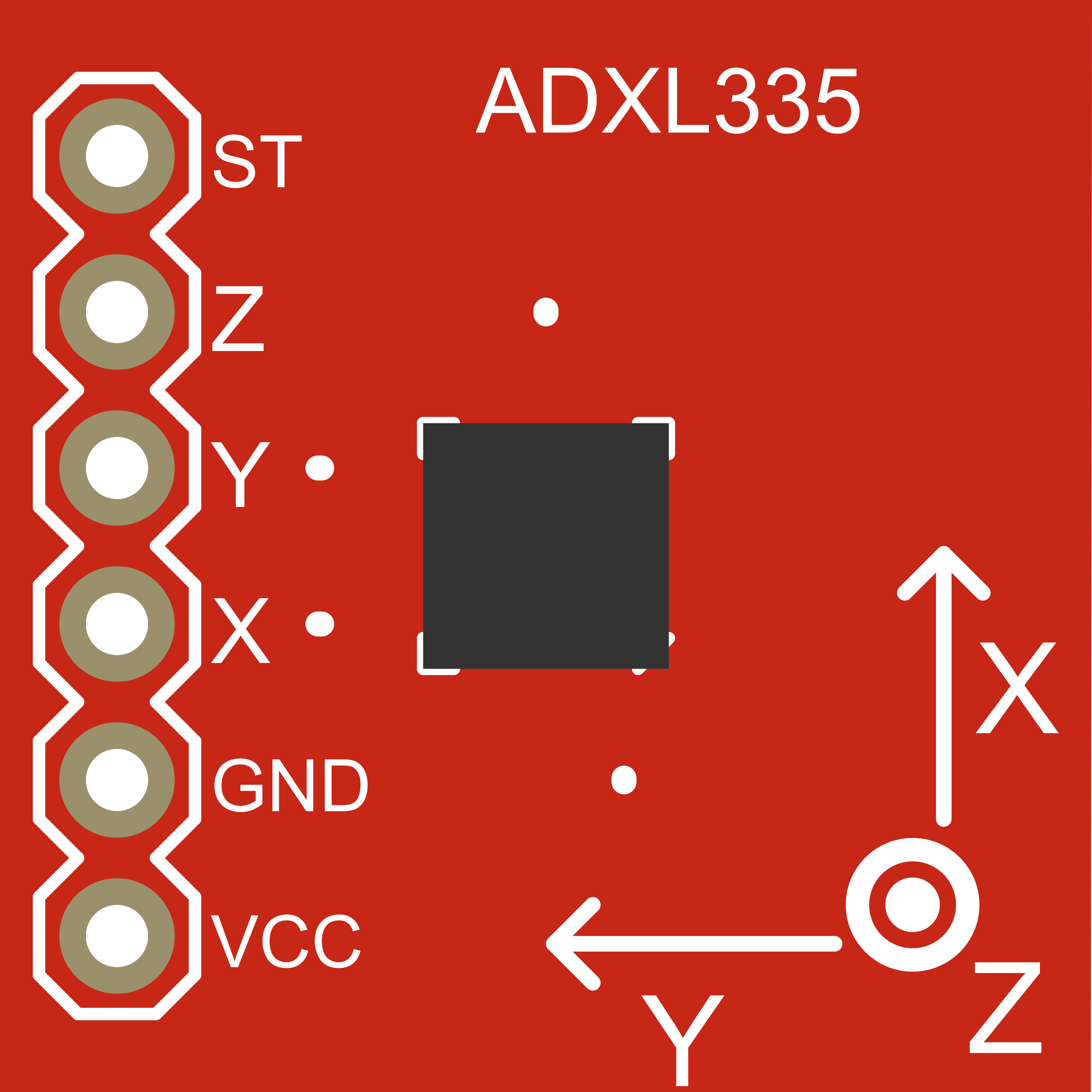
Pin Configuration and Descriptions

Pin Number Name Description
1 VCC Power supply (1.8V to 3.6V)
2 X-OUT Analog voltage output for X-axis
3 Y-OUT Analog voltage output for Y-axis
4 Z-OUT Analog voltage output for Z-axis
5 GND Ground reference for the power supply
6 ST Self-test pin (leave unconnected if not used)

Usage Instructions

Interfacing with a Microcontroller

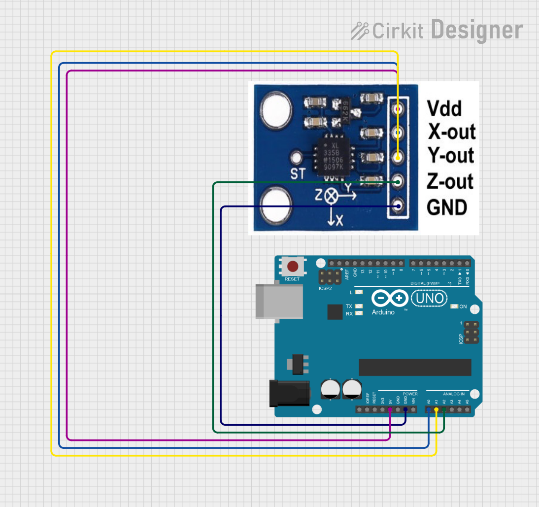
To use the ADXL335 with a microcontroller like the Arduino UNO, follow these steps:

  1. Connect VCC to the 3.3V output on the Arduino.
  2. Connect GND to one of the GND pins on the Arduino.
  3. Connect X-OUT, Y-OUT, and Z-OUT to three analog input pins on the Arduino (e.g., A0, A1, A2).
  4. If using the self-test feature, connect ST to a digital output pin; otherwise, leave it unconnected.

Calibration

Before using the accelerometer, it is important to calibrate it to ensure accurate readings. This involves reading the outputs at a known orientation (e.g., lying flat) and adjusting the readings to account for zero-g bias and sensitivity.

Best Practices

  • Use capacitors for noise reduction if the application is sensitive to noise.
  • Avoid physical shock and vibration that exceed the specified limits.
  • Ensure that the power supply is stable and within the specified voltage range.

Example Arduino Code

// Define the analog pins connected to the accelerometer
const int xPin = A0;
const int yPin = A1;
const int zPin = A2;

void setup() {
  // Initialize the serial communication
  Serial.begin(9600);
}

void loop() {
  // Read the analog values from the accelerometer
  int xVal = analogRead(xPin);
  int yVal = analogRead(yPin);
  int zVal = analogRead(zPin);

  // Convert the analog values to 'g' values
  float xG = ((float)xVal - 341.5) / 68.5; // 341.5 and 68.5 are calibration values
  float yG = ((float)yVal - 341.5) / 68.5; // Replace with your calibrated values
  float zG = ((float)zVal - 341.5) / 68.5;

  // Print the results
  Serial.print("X: ");
  Serial.print(xG);
  Serial.print("g, Y: ");
  Serial.print(yG);
  Serial.print("g, Z: ");
  Serial.print(zG);
  Serial.println("g");

  // Delay before the next reading
  delay(100);
}

Troubleshooting and FAQs

Common Issues

  • Inaccurate Readings: Ensure that the accelerometer is properly calibrated. Check for any mechanical stress or thermal variation that may affect the sensor.
  • Noisy Signal: Use capacitors to filter the noise, and keep the power supply stable. Avoid long wires to reduce electromagnetic interference.
  • Unresponsive Sensor: Check the connections and ensure that the power supply is within the specified range.

FAQs

Q: Can the ADXL335 measure rotation? A: No, the ADXL335 measures linear acceleration. For rotation, you would need a gyroscope.

Q: What is the purpose of the self-test pin? A: The self-test pin is used to verify the functionality of the accelerometer. When activated, it applies a known force to the sensor for testing purposes.

Q: How do I convert the analog readings to 'g' values? A: The analog readings can be converted to 'g' values by first subtracting the zero-g bias level and then dividing by the sensitivity. Calibration is necessary to determine the exact values for these calculations.

Q: Can I use the ADXL335 with a 5V microcontroller? A: Yes, but ensure that the VCC is connected to a 3.3V supply, and use voltage dividers or level shifters for the analog outputs if the microcontroller's analog inputs are not 3.3V tolerant.