How to Use CJMCU-811: Examples, Pinouts, and Specs
Introduction
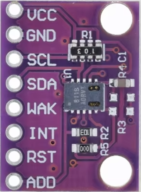
The CJMCU-811 is an electronic sensor module designed for the measurement of Carbon Dioxide (CO2) concentration levels in indoor environments. This compact module is based on the CCS811 sensor, which is an ultra-low power digital gas sensor solution. The CJMCU-811 is ideal for use in applications such as air quality monitoring, HVAC systems, and smart home automation.
Explore Projects Built with CJMCU-811

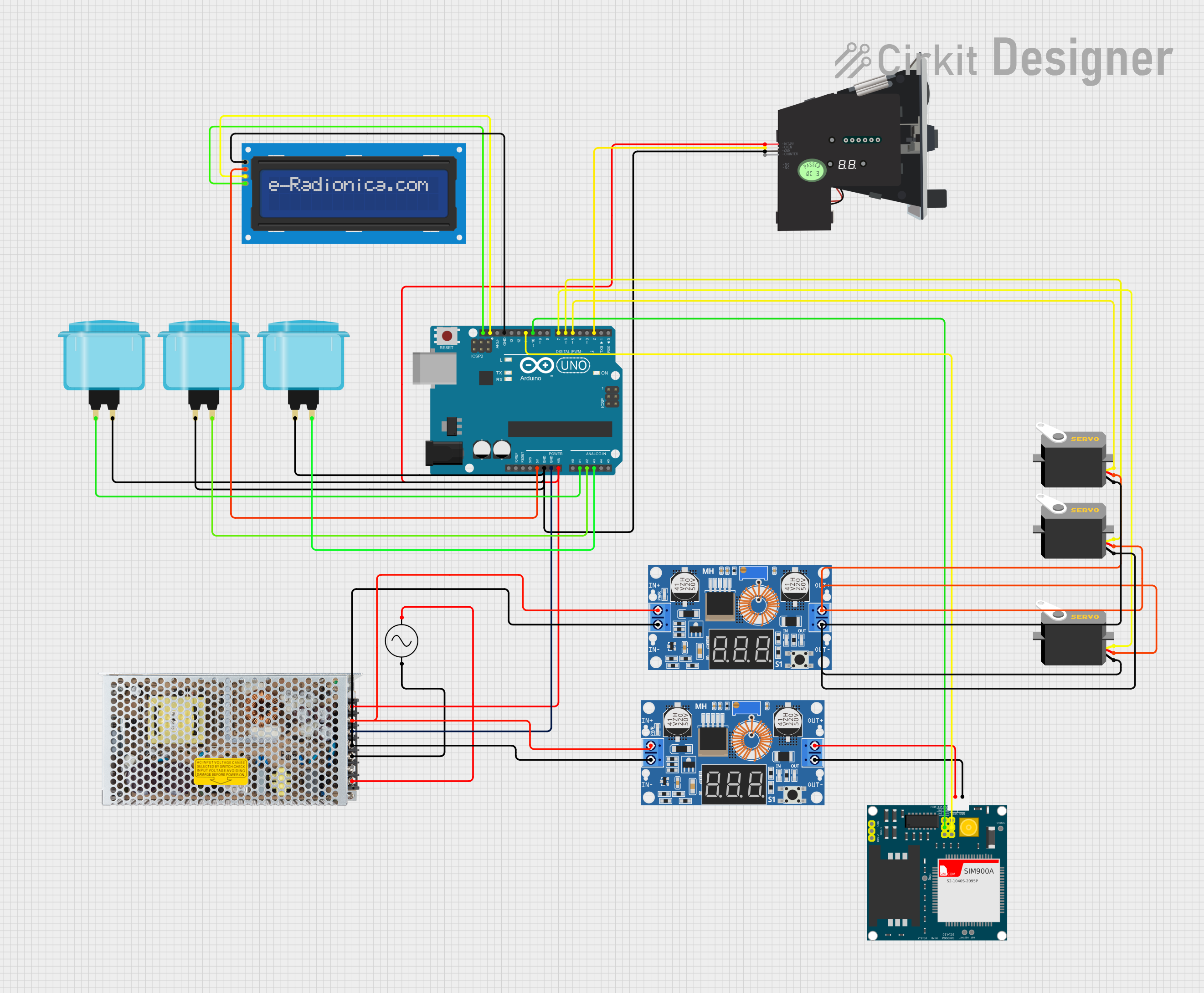
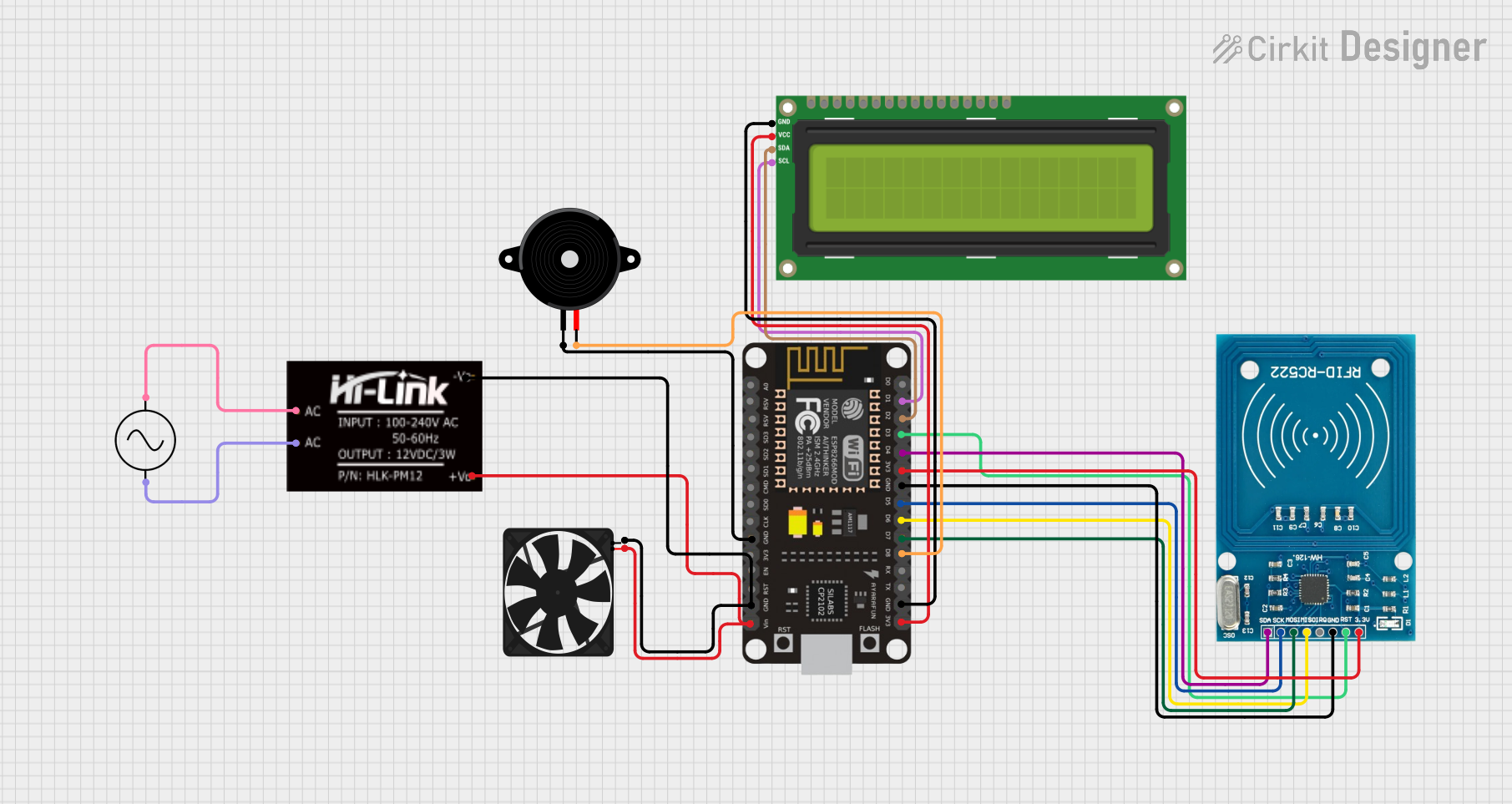
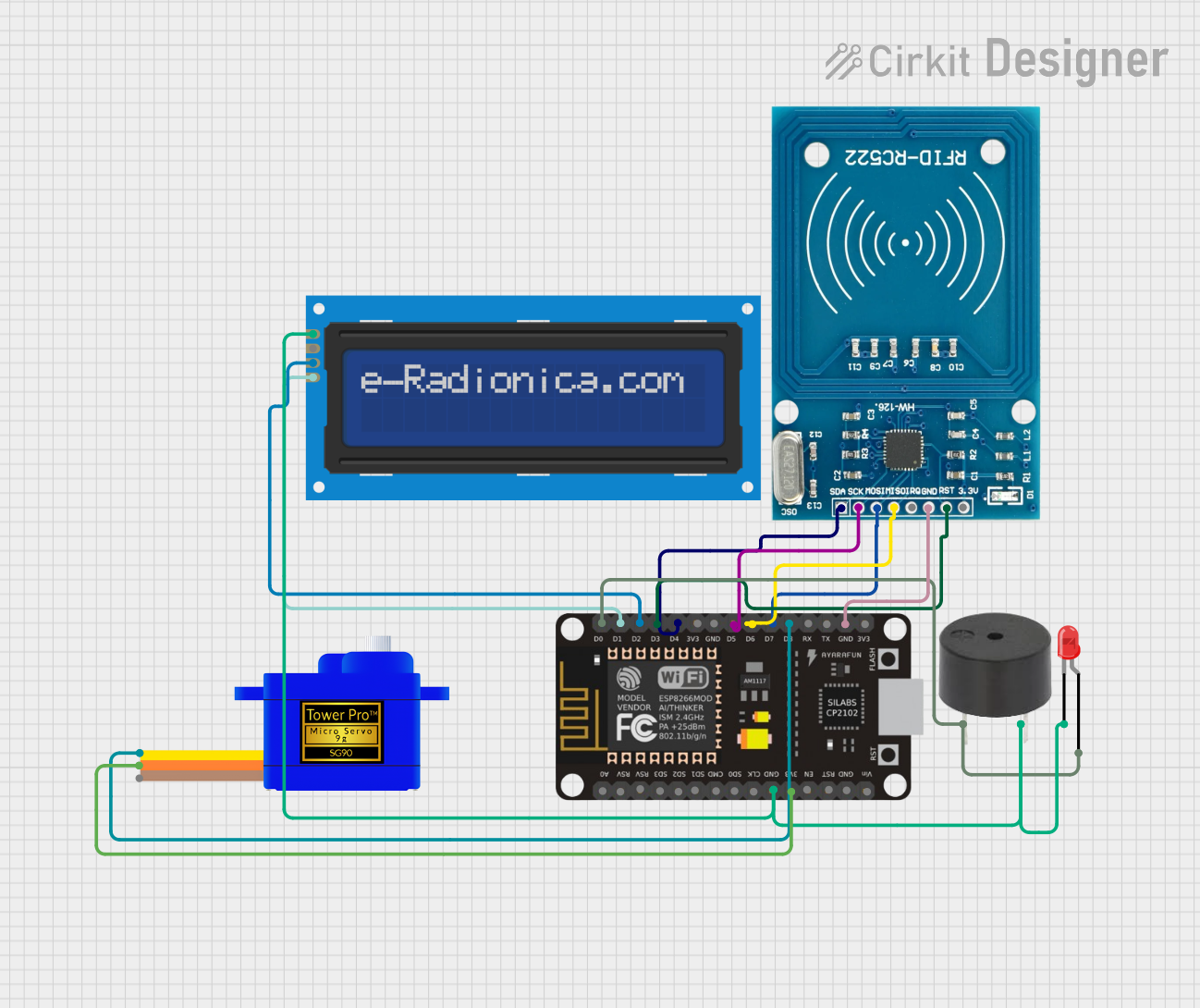
Explore Projects Built with CJMCU-811
Common Applications and Use Cases
- Indoor air quality monitoring
- Environmental monitoring
- Smart home devices
- HVAC systems control
- IoT applications for health and safety
Technical Specifications
Key Technical Details
- Measurement Range: 400 to 8192 ppm
- Interface: I2C
- Supply Voltage: 3.3V
- Current Consumption: 1.2mA (measurement mode), 10µA (sleep mode)
- Operating Temperature: -40°C to 85°C
Pin Configuration and Descriptions
| Pin Number | Pin Name | Description |
|---|---|---|
| 1 | VCC | Power supply (3.3V) |
| 2 | GND | Ground |
| 3 | SDA | I2C Data |
| 4 | SCL | I2C Clock |
| 5 | WAKE | Wake pin (active low) |
| 6 | INT | Interrupt pin |
| 7 | RST | Reset pin (active low) |
| 8 | ADDR | I2C Address selection (floating/low) |
Usage Instructions
How to Use the Component in a Circuit
- Power Supply: Connect the VCC pin to a 3.3V power source and the GND pin to the ground.
- I2C Communication: Connect the SDA and SCL pins to the I2C data and clock lines, respectively.
- Wake and Reset: The WAKE pin should be connected to ground to keep the sensor awake. The RST pin can be left floating or connected to a microcontroller pin for manual reset control.
- Interrupts: The INT pin can be connected to a microcontroller interrupt pin to receive alerts when new data is available.
- Address Selection: The ADDR pin can be left floating for the default I2C address or connected to ground for an alternate address.
Important Considerations and Best Practices
- Ensure that the power supply is stable and does not exceed 3.3V.
- Use pull-up resistors on the I2C data and clock lines if they are not already provided in the microcontroller board.
- Avoid exposing the sensor to volatile organic compounds (VOCs) and solvents during soldering or operation.
- Calibrate the sensor according to the manufacturer's instructions for accurate readings.
- Implement proper ESD precautions when handling the sensor module.
Example Code for Arduino UNO
#include <Wire.h>

// CJMCU-811 I2C address (default)
#define CJMCU_811_ADDRESS 0x5A

void setup() {
  Wire.begin(); // Initialize I2C
  Serial.begin(9600); // Start serial communication at 9600 baud rate

  // Wake up CJMCU-811 sensor
  pinMode(2, OUTPUT); // Use digital pin 2 to control WAKE
  digitalWrite(2, LOW); // Set to LOW to wake up the sensor
}

void loop() {
  // Read CO2 concentration from CJMCU-811
  Wire.beginTransmission(CJMCU_811_ADDRESS);
  Wire.write(0x02); // Point to the data register
  Wire.endTransmission();
  Wire.requestFrom(CJMCU_811_ADDRESS, 4); // Request 4 bytes of data

  if (Wire.available() == 4) {
    // Read the data - high byte first
    int co2High = Wire.read();
    int co2Low = Wire.read();
    int co2 = (co2High << 8) + co2Low;

    // Output the CO2 concentration to the serial monitor
    Serial.print("CO2 Concentration: ");
    Serial.print(co2);
    Serial.println(" ppm");
  }

  delay(2000); // Wait for 2 seconds before reading again
}
Troubleshooting and FAQs
Common Issues Users Might Face
- Inaccurate Readings: If the sensor provides inaccurate readings, ensure that it has been properly calibrated and that there are no sources of VOCs or solvents nearby.
- No Data on I2C: Check the connections and ensure that the correct I2C address is being used. Also, verify that the sensor is properly powered and not in sleep mode.
Solutions and Tips for Troubleshooting
- Sensor Not Responding: Reset the sensor using the RST pin or power cycle the module.
- I2C Communication Issues: Use an I2C scanner sketch to check if the sensor is detected on the I2C bus.
- Intermittent Readings: Ensure that the WAKE pin is held low during operation and that there are no loose connections.
FAQs
Q: Can the CJMCU-811 be used with a 5V microcontroller? A: Yes, but level shifters should be used on the I2C lines to protect the sensor.
Q: How often should the sensor be calibrated? A: Calibration frequency depends on the application, but typically once before initial use and periodically according to the manufacturer's recommendations.
Q: What is the default I2C address of the CJMCU-811? A: The default I2C address is 0x5A. If the ADDR pin is connected to ground, the alternate address is 0x5B.
Q: How long does the sensor need to warm up? A: The sensor requires a warm-up period of at least 20 minutes for stable operation after being powered on.