Cirkit Designer Logo
Cirkit Designer
Your all-in-one circuit design IDE
Home / 
Component Documentation

How to Use mcp6002: Examples, Pinouts, and Specs

Image of mcp6002
Cirkit Designer LogoDesign with mcp6002 in Cirkit Designer

Introduction

The MCP6002 is a dual operational amplifier (op-amp) manufactured by Microchip. It is designed for low-power applications, making it ideal for battery-operated devices. With its wide supply voltage range, high input impedance, and low output noise, the MCP6002 is well-suited for a variety of analog signal processing tasks, including signal amplification, filtering, and buffering.

Explore Projects Built with mcp6002

Use Cirkit Designer to design, explore, and prototype these projects online. Some projects support real-time simulation. Click "Open Project" to start designing instantly!
I2C-Controlled Relay Switching with ESP32 and MCP23017 for Home Automation
Image of Vloerverwarming: A project utilizing mcp6002 in a practical application
This circuit appears to be a control system utilizing two MCP23017 I/O expanders interfaced with an Olimex ESP32-EVB microcontroller via I2C communication, as indicated by the SDA and SCL connections with pull-up resistors. The MCP23017 expanders control an 8-channel relay module, allowing the microcontroller to switch various loads, potentially for home automation or industrial control. Additionally, there is an Adafruit ADS1115 16-bit ADC for analog signal measurement, and several heating actuators and a thermostat are connected, suggesting temperature control functionality.
Cirkit Designer LogoOpen Project in Cirkit Designer
Wi-Fi Controlled Relay Module with ESP8266 and MCP23017
Image of smart home: A project utilizing mcp6002 in a practical application
This circuit is a WiFi-enabled relay control system using an ESP8266-01 module and an MCP23017 I/O expander. The ESP8266 communicates with the MCP23017 via I2C to control an 8-channel relay module based on the state of 8 rocker switches, allowing for remote and manual control of connected devices.
Cirkit Designer LogoOpen Project in Cirkit Designer
ESP32 and MCP23017-Based Smart Relay Control System with DHT22 Sensors
Image of Indoor Lounge: A project utilizing mcp6002 in a practical application
This circuit is a control system that uses an ESP32 microcontroller to manage multiple relays and read data from DHT22 temperature and humidity sensors. The DFRobot Gravity MCP23017 I2C module expands the GPIO capabilities of the ESP32, allowing it to control additional relays for switching high-power devices.
Cirkit Designer LogoOpen Project in Cirkit Designer
MCP23017-Expanded I/O Interface with ADS1115 ADC and ESP32 Control
Image of door and window sensors: A project utilizing mcp6002 in a practical application
This circuit features two MCP23017 I/O expanders interfaced with multiple switches, allowing for the expansion of input capabilities. The MCP23017s are connected via I2C to an Olimex ESP32-EVB microcontroller, which likely manages the input states from the switches. Additionally, an Adafruit ADS1115 16-bit ADC is included, suggesting that some analog inputs are being monitored, with the ADC also interfaced with the ESP32 via I2C.
Cirkit Designer LogoOpen Project in Cirkit Designer

Explore Projects Built with mcp6002

Use Cirkit Designer to design, explore, and prototype these projects online. Some projects support real-time simulation. Click "Open Project" to start designing instantly!
Image of Vloerverwarming: A project utilizing mcp6002 in a practical application
I2C-Controlled Relay Switching with ESP32 and MCP23017 for Home Automation
This circuit appears to be a control system utilizing two MCP23017 I/O expanders interfaced with an Olimex ESP32-EVB microcontroller via I2C communication, as indicated by the SDA and SCL connections with pull-up resistors. The MCP23017 expanders control an 8-channel relay module, allowing the microcontroller to switch various loads, potentially for home automation or industrial control. Additionally, there is an Adafruit ADS1115 16-bit ADC for analog signal measurement, and several heating actuators and a thermostat are connected, suggesting temperature control functionality.
Cirkit Designer LogoOpen Project in Cirkit Designer
Image of smart home: A project utilizing mcp6002 in a practical application
Wi-Fi Controlled Relay Module with ESP8266 and MCP23017
This circuit is a WiFi-enabled relay control system using an ESP8266-01 module and an MCP23017 I/O expander. The ESP8266 communicates with the MCP23017 via I2C to control an 8-channel relay module based on the state of 8 rocker switches, allowing for remote and manual control of connected devices.
Cirkit Designer LogoOpen Project in Cirkit Designer
Image of Indoor Lounge: A project utilizing mcp6002 in a practical application
ESP32 and MCP23017-Based Smart Relay Control System with DHT22 Sensors
This circuit is a control system that uses an ESP32 microcontroller to manage multiple relays and read data from DHT22 temperature and humidity sensors. The DFRobot Gravity MCP23017 I2C module expands the GPIO capabilities of the ESP32, allowing it to control additional relays for switching high-power devices.
Cirkit Designer LogoOpen Project in Cirkit Designer
Image of door and window sensors: A project utilizing mcp6002 in a practical application
MCP23017-Expanded I/O Interface with ADS1115 ADC and ESP32 Control
This circuit features two MCP23017 I/O expanders interfaced with multiple switches, allowing for the expansion of input capabilities. The MCP23017s are connected via I2C to an Olimex ESP32-EVB microcontroller, which likely manages the input states from the switches. Additionally, an Adafruit ADS1115 16-bit ADC is included, suggesting that some analog inputs are being monitored, with the ADC also interfaced with the ESP32 via I2C.
Cirkit Designer LogoOpen Project in Cirkit Designer

Common Applications

  • Portable and battery-powered devices
  • Sensor signal conditioning
  • Active filters and integrators
  • Analog-to-digital converter (ADC) buffering
  • Audio signal processing

Technical Specifications

The MCP6002 offers excellent performance for low-power applications. Below are its key technical specifications:

Parameter Value
Supply Voltage Range 1.8V to 6.0V
Supply Current (per op-amp) 100 µA (typical)
Input Offset Voltage ±4.5 mV (maximum)
Input Impedance 10⁶ GΩ (typical)
Gain Bandwidth Product 1 MHz (typical)
Slew Rate 0.6 V/µs (typical)
Output Voltage Swing Rail-to-rail
Operating Temperature Range -40°C to +85°C
Package Options PDIP, SOIC, MSOP

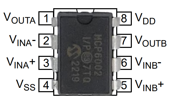
Pin Configuration and Descriptions

The MCP6002 is available in an 8-pin package. Below is the pinout and description:

Pin Number Pin Name Description
1 OUTA Output of Op-Amp A
2 INA- Inverting Input of Op-Amp A
3 INA+ Non-Inverting Input of Op-Amp A
4 VSS Ground (Negative Power Supply)
5 INB+ Non-Inverting Input of Op-Amp B
6 INB- Inverting Input of Op-Amp B
7 OUTB Output of Op-Amp B
8 VDD Positive Power Supply

Usage Instructions

The MCP6002 is straightforward to use in a variety of analog circuits. Below are the steps and considerations for integrating it into your design:

Basic Circuit Configuration

  1. Power Supply: Connect the VDD pin to a positive voltage source (1.8V to 6.0V) and the VSS pin to ground.
  2. Input Connections:
    • For each op-amp, connect the INA+ or INB+ pin to the non-inverting input signal.
    • Connect the INA- or INB- pin to the inverting input signal or feedback network.
  3. Output Connections: The OUTA and OUTB pins provide the amplified output signals.

Example: Voltage Follower (Buffer)

The MCP6002 can be used as a voltage follower to buffer a high-impedance signal. Below is an example circuit and Arduino code for using the MCP6002 with an Arduino UNO to read an analog sensor:

Circuit Diagram

  • Connect the sensor output to the INA+ pin.
  • Connect the INA- pin directly to the OUTA pin (feedback loop).
  • Connect the OUTA pin to the Arduino UNO's analog input (e.g., A0).
  • Power the MCP6002 with 5V (VDD) and ground (VSS) from the Arduino.

Arduino Code

// MCP6002 Voltage Follower Example
// This code reads an analog signal from the MCP6002 and prints the value to the Serial Monitor.

const int analogPin = A0; // Analog pin connected to MCP6002 OUTA

void setup() {
  Serial.begin(9600); // Initialize serial communication at 9600 baud
}

void loop() {
  int sensorValue = analogRead(analogPin); // Read the analog value
  float voltage = sensorValue * (5.0 / 1023.0); // Convert to voltage
  Serial.print("Sensor Voltage: ");
  Serial.println(voltage); // Print the voltage to the Serial Monitor
  delay(500); // Wait for 500ms before the next reading
}

Important Considerations

  • Power Supply Decoupling: Place a 0.1 µF ceramic capacitor close to the VDD pin to reduce noise and improve stability.
  • Input Voltage Range: Ensure the input voltage stays within the op-amp's common-mode input range (0V to VDD).
  • Output Loading: Avoid driving heavy loads directly from the output. Use a buffer or additional circuitry if needed.

Troubleshooting and FAQs

Common Issues and Solutions

  1. No Output Signal:

    • Verify that the power supply connections (VDD and VSS) are correct.
    • Check for proper input signal connections and ensure they are within the specified range.
  2. Distorted Output:

    • Ensure the load connected to the output is not too low in impedance.
    • Verify that the input signal is not exceeding the op-amp's input voltage range.
  3. High Noise in Output:

    • Add decoupling capacitors (e.g., 0.1 µF) near the power supply pins.
    • Use proper grounding techniques to minimize noise.
  4. Op-Amp Overheating:

    • Check for excessive current draw due to incorrect wiring or short circuits.
    • Ensure the supply voltage does not exceed the maximum rating (6.0V).

FAQs

Q: Can the MCP6002 operate with a single supply?
A: Yes, the MCP6002 is designed to operate with a single supply voltage as low as 1.8V.

Q: Is the MCP6002 suitable for audio applications?
A: Yes, its low noise and rail-to-rail output make it suitable for basic audio signal processing.

Q: Can I use the MCP6002 for high-frequency applications?
A: The MCP6002 has a gain bandwidth product of 1 MHz, so it is best suited for low- to mid-frequency applications.

Q: What is the maximum output current of the MCP6002?
A: The MCP6002 can source or sink up to 23 mA (typical), but it is recommended to use it with lighter loads for optimal performance.