
How to Use Mini ESP32 S3 Custome: Examples, Pinouts, and Specs
 Design with Mini ESP32 S3 Custome in Cirkit Designer
Introduction
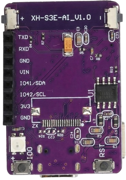
The Mini ESP32 S3 Custom is a compact microcontroller designed for IoT applications and projects requiring wireless connectivity. It integrates both Wi-Fi and Bluetooth capabilities, making it a versatile choice for smart devices, home automation, wearable electronics, and other connected systems. Its small form factor and powerful processing capabilities make it ideal for space-constrained designs while maintaining excellent performance.
Explore Projects Built with Mini ESP32 S3 Custome
 Open Project in Cirkit Designer
 Open Project in Cirkit Designer
 Open Project in Cirkit Designer
 Open Project in Cirkit Designer
Explore Projects Built with Mini ESP32 S3 Custome
Open Project in Cirkit DesignerOpen Project in Cirkit DesignerOpen Project in Cirkit DesignerOpen Project in Cirkit DesignerCommon Applications and Use Cases
- IoT devices and smart home systems
- Wearable electronics
- Wireless sensor networks
- Robotics and automation
- Prototyping and development of connected devices
- Data logging and remote monitoring
Technical Specifications
The Mini ESP32 S3 Custom is built on the ESP32-S3 chip, offering advanced features for wireless communication and processing. Below are the key technical details:
Key Specifications
| Parameter | Value |
|---|---|
| Microcontroller | ESP32-S3 |
| CPU | Dual-core Xtensa LX7, up to 240 MHz |
| Flash Memory | 4 MB (expandable in some variants) |
| SRAM | 512 KB |
| Wireless Connectivity | Wi-Fi 802.11 b/g/n, Bluetooth 5.0 LE |
| GPIO Pins | 21 (configurable for various functions) |
| Operating Voltage | 3.3V |
| Input Voltage Range | 5V (via USB) or 3.3V (via pin) |
| Power Consumption | Ultra-low power modes available |
| Interfaces | UART, SPI, I2C, I2S, PWM, ADC, DAC |
| ADC Resolution | 12-bit |
| Dimensions | 25mm x 18mm |
Pin Configuration and Descriptions
The Mini ESP32 S3 Custom features a compact pinout. Below is the pin configuration:
| Pin Number | Pin Name | Description |
|---|---|---|
| 1 | GND | Ground |
| 2 | 3V3 | 3.3V Power Output |
| 3 | EN | Enable Pin (Active High) |
| 4 | GPIO0 | General Purpose I/O, Boot Mode Selection |
| 5 | GPIO1 | General Purpose I/O |
| 6 | GPIO2 | General Purpose I/O |
| 7 | GPIO3 | General Purpose I/O |
| 8 | TXD0 | UART0 Transmit |
| 9 | RXD0 | UART0 Receive |
| 10 | GPIO4 | General Purpose I/O |
| 11 | GPIO5 | General Purpose I/O |
| 12 | GPIO6 | General Purpose I/O |
| 13 | GPIO7 | General Purpose I/O |
| 14 | GPIO8 | General Purpose I/O |
| 15 | GPIO9 | General Purpose I/O |
| 16 | GPIO10 | General Purpose I/O |
| 17 | GPIO11 | General Purpose I/O |
| 18 | GPIO12 | General Purpose I/O |
| 19 | GPIO13 | General Purpose I/O |
| 20 | GPIO14 | General Purpose I/O |
| 21 | GPIO15 | General Purpose I/O |
Usage Instructions
How to Use the Mini ESP32 S3 Custom in a Circuit
Powering the Module:
- Connect the
5Vpin to a 5V power source (e.g., USB) or the3V3pin to a regulated 3.3V supply. - Ensure the
GNDpin is connected to the ground of your circuit.
- Connect the
Programming the Module:
- Use a USB-to-serial adapter to connect the module to your computer.
- Install the necessary drivers for the ESP32-S3.
- Use the Arduino IDE or ESP-IDF (Espressif IoT Development Framework) for programming.
Connecting Peripherals:
- Use the GPIO pins for interfacing with sensors, actuators, or other devices.
- Configure the pins in your code for the desired functionality (e.g., input, output, PWM).
Wireless Connectivity:
- Configure Wi-Fi and Bluetooth settings in your code to enable wireless communication.
- Use libraries like
WiFi.horBluetoothSerial.hin the Arduino IDE.
Important Considerations and Best Practices
- Voltage Levels: Ensure all connected peripherals operate at 3.3V logic levels to avoid damaging the module.
- Boot Mode: To enter bootloader mode, hold the
GPIO0pin low while resetting the module. - Antenna Placement: Avoid placing metal objects near the onboard antenna to ensure optimal wireless performance.
- Power Supply: Use a stable power source to prevent unexpected resets or performance issues.
Example Code for Arduino UNO
Below is an example of how to connect the Mini ESP32 S3 Custom to a Wi-Fi network using the Arduino IDE:
#include <WiFi.h> // Include the Wi-Fi library

const char* ssid = "Your_SSID";       // Replace with your Wi-Fi network name
const char* password = "Your_PASSWORD"; // Replace with your Wi-Fi password

void setup() {
  Serial.begin(115200); // Initialize serial communication
  delay(1000);

  Serial.println("Connecting to Wi-Fi...");
  WiFi.begin(ssid, password); // Start Wi-Fi connection

  while (WiFi.status() != WL_CONNECTED) {
    delay(500);
    Serial.print("."); // Print dots while connecting
  }

  Serial.println("\nWi-Fi connected!");
  Serial.print("IP Address: ");
  Serial.println(WiFi.localIP()); // Print the assigned IP address
}

void loop() {
  // Add your main code here
}
Troubleshooting and FAQs
Common Issues and Solutions
Module Not Detected by Computer:
- Ensure the USB cable is functional and supports data transfer.
- Install the correct drivers for the ESP32-S3.
Wi-Fi Connection Fails:
- Double-check the SSID and password in your code.
- Ensure the Wi-Fi network is operational and within range.
Unexpected Resets:
- Verify the power supply is stable and sufficient for the module.
- Check for loose connections or short circuits.
GPIO Pins Not Responding:
- Confirm the pins are correctly configured in your code.
- Ensure no conflicting peripherals are connected to the same pins.
FAQs
Q: Can I use the Mini ESP32 S3 Custom with a 5V logic device?
A: No, the GPIO pins operate at 3.3V logic levels. Use a level shifter if interfacing with 5V devices.
Q: How do I update the firmware?
A: Use the ESP-IDF or Arduino IDE to upload new firmware via the USB interface.
Q: Does the module support deep sleep mode?
A: Yes, the Mini ESP32 S3 Custom supports ultra-low power modes, including deep sleep, for energy-efficient applications.
Q: Can I use the module for Bluetooth audio streaming?
A: Yes, the ESP32-S3 supports Bluetooth audio features, but additional configuration and libraries may be required.