How to Use PZEM-004T V3: Examples, Pinouts, and Specs
Introduction
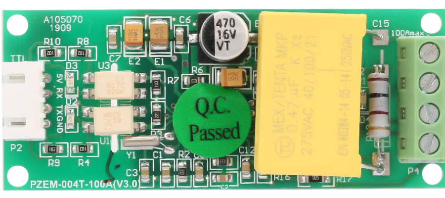
The PZEM-004T V3, manufactured by Peacefair, is a multifunctional energy monitoring module designed for AC circuits. It is capable of measuring key electrical parameters such as voltage, current, power, energy, and frequency. The module communicates via UART (Universal Asynchronous Receiver-Transmitter), making it easy to interface with microcontrollers, such as Arduino, Raspberry Pi, and other embedded systems.
Explore Projects Built with PZEM-004T V3


Explore Projects Built with PZEM-004T V3
Common Applications and Use Cases
- Home energy monitoring systems
- Industrial power consumption analysis
- Smart energy meters
- Renewable energy systems (e.g., solar or wind power monitoring)
- IoT-based energy management solutions
Technical Specifications
The following table outlines the key technical specifications of the PZEM-004T V3:
| Parameter | Specification |
|---|---|
| Operating Voltage | 5V DC |
| Measurement Voltage | 80V - 260V AC |
| Measurement Current | 0 - 100A (with external current transformer) |
| Power Measurement | 0 - 22kW |
| Energy Measurement | 0 - 9999 kWh |
| Frequency Range | 45Hz - 65Hz |
| Communication Protocol | UART (9600 baud rate, 8N1 format) |
| Accuracy | ±0.5% |
| Dimensions | 48mm x 24mm x 25mm |
Pin Configuration and Descriptions
The PZEM-004T V3 has a 4-pin interface for communication and power, as well as terminals for AC input and the current transformer (CT). The pin configuration is as follows:
UART Interface
| Pin | Name | Description |
|---|---|---|
| 1 | VCC | Power supply input (5V DC) |
| 2 | GND | Ground connection |
| 3 | RX | UART Receive pin (connect to TX of MCU) |
| 4 | TX | UART Transmit pin (connect to RX of MCU) |
AC Input and Current Transformer
| Terminal | Name | Description |
|---|---|---|
| L | Line (Live) | Connect to the live wire of the AC circuit |
| N | Neutral | Connect to the neutral wire of the AC circuit |
| CT | Current Transformer | Connect to the external CT clamp |
Usage Instructions
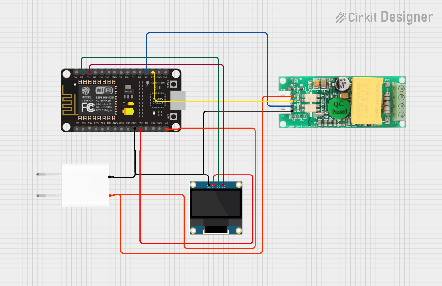
How to Use the PZEM-004T V3 in a Circuit
- Power the Module: Connect the VCC and GND pins to a 5V DC power source.
- Connect the AC Circuit:
- Attach the live (L) and neutral (N) wires of the AC circuit to the respective terminals on the module.
- Place the external current transformer (CT) around the live wire of the AC circuit.
- Establish UART Communication:
- Connect the RX pin of the PZEM-004T V3 to the TX pin of your microcontroller.
- Connect the TX pin of the PZEM-004T V3 to the RX pin of your microcontroller.
- Configure the Microcontroller:
- Use a UART library or serial communication functions to send and receive data from the module.
- Ensure the UART settings are configured to 9600 baud rate, 8 data bits, no parity, and 1 stop bit (8N1).
Important Considerations and Best Practices
- Safety First: Always handle AC circuits with care. Ensure the circuit is powered off before making connections.
- Current Transformer Placement: The CT clamp must be placed around the live wire only, not both live and neutral wires.
- Voltage Range: Ensure the AC voltage is within the module's measurement range (80V - 260V AC).
- Isolation: Use proper electrical isolation techniques when interfacing the module with microcontrollers to prevent damage.
Example Code for Arduino UNO
Below is an example Arduino sketch to read data from the PZEM-004T V3:
#include <SoftwareSerial.h>

// Define RX and TX pins for SoftwareSerial
SoftwareSerial pzemSerial(10, 11); // RX = pin 10, TX = pin 11

void setup() {
  Serial.begin(9600); // Initialize Serial Monitor
  pzemSerial.begin(9600); // Initialize communication with PZEM-004T V3

  Serial.println("PZEM-004T V3 Energy Monitor");
}

void loop() {
  // Request data from the PZEM-004T V3
  byte request[] = {0xB0, 0xC0, 0xA8, 0x01, 0x01}; // Example request packet
  pzemSerial.write(request, sizeof(request));

  delay(100); // Wait for the module to respond

  // Read response from the module
  byte response[7];
  int bytesRead = pzemSerial.readBytes(response, 7);

  if (bytesRead == 7) {
    // Parse the response (example: voltage, current, power, etc.)
    float voltage = (response[1] << 8 | response[2]) / 10.0;
    float current = (response[3] << 8 | response[4]) / 100.0;
    float power = (response[5] << 8 | response[6]) / 10.0;

    // Print the values to the Serial Monitor
    Serial.print("Voltage: ");
    Serial.print(voltage);
    Serial.println(" V");

    Serial.print("Current: ");
    Serial.print(current);
    Serial.println(" A");

    Serial.print("Power: ");
    Serial.print(power);
    Serial.println(" W");
  } else {
    Serial.println("Failed to read data from PZEM-004T V3");
  }

  delay(1000); // Wait 1 second before the next reading
}
Troubleshooting and FAQs
Common Issues and Solutions
No Data Received from the Module:
- Ensure the RX and TX pins are correctly connected (crossed: RX to TX, TX to RX).
- Verify the UART settings (9600 baud rate, 8N1 format).
- Check the power supply to the module (5V DC).
Incorrect Measurements:
- Ensure the CT clamp is properly placed around the live wire only.
- Verify that the AC voltage is within the specified range (80V - 260V AC).
Module Not Responding:
- Check the wiring connections for loose or incorrect connections.
- Ensure the microcontroller's UART pins are not being used by other peripherals.
FAQs
Q: Can the PZEM-004T V3 measure DC circuits?
A: No, the module is designed specifically for AC circuits and cannot measure DC voltage or current.
Q: Can I use the module with a 3.3V microcontroller?
A: Yes, but you may need a level shifter to safely interface the 5V UART signals with the 3.3V logic levels.
Q: How do I reset the energy counter?
A: The energy counter can be reset by sending a specific command via UART. Refer to the module's communication protocol documentation for details.