How to Use Button Limit Switch: Examples, Pinouts, and Specs
Introduction
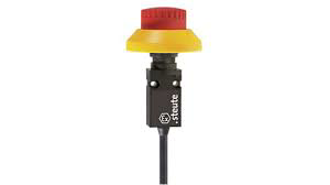
A Button Limit Switch is a type of switch that is activated by physical contact. It is typically used to detect the presence or absence of an object or to limit the movement of a machine part. These switches are commonly found in industrial machinery, robotics, and various automation systems. They provide a reliable means of ensuring that mechanical components do not exceed their intended range of motion, thereby preventing potential damage or operational errors.
Explore Projects Built with Button Limit Switch
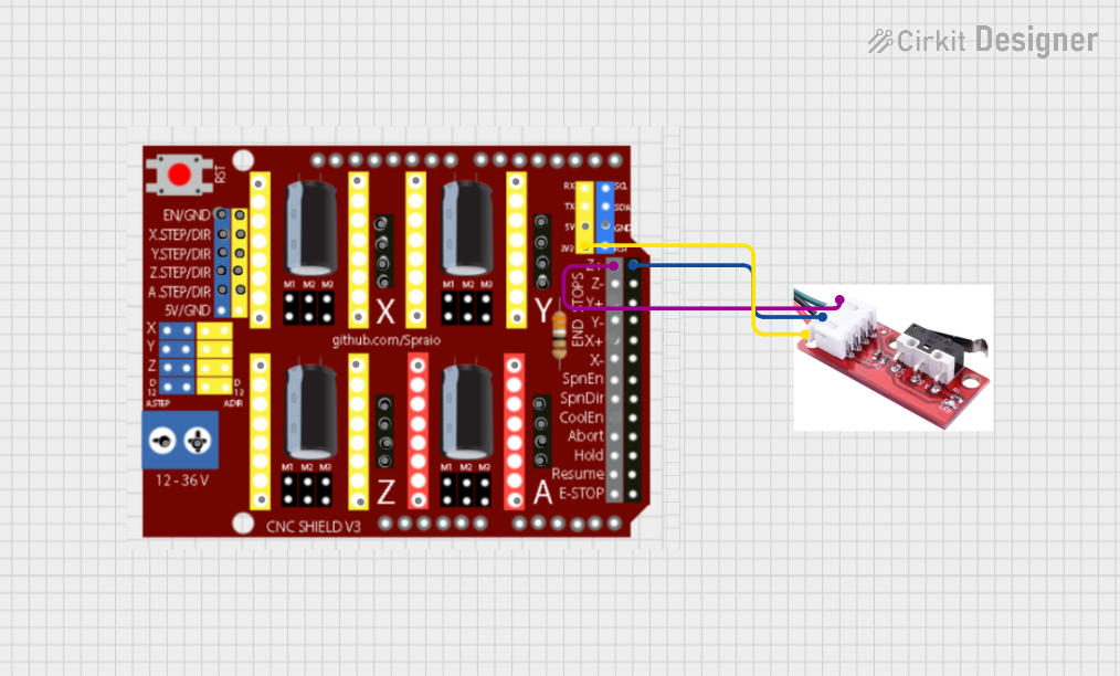
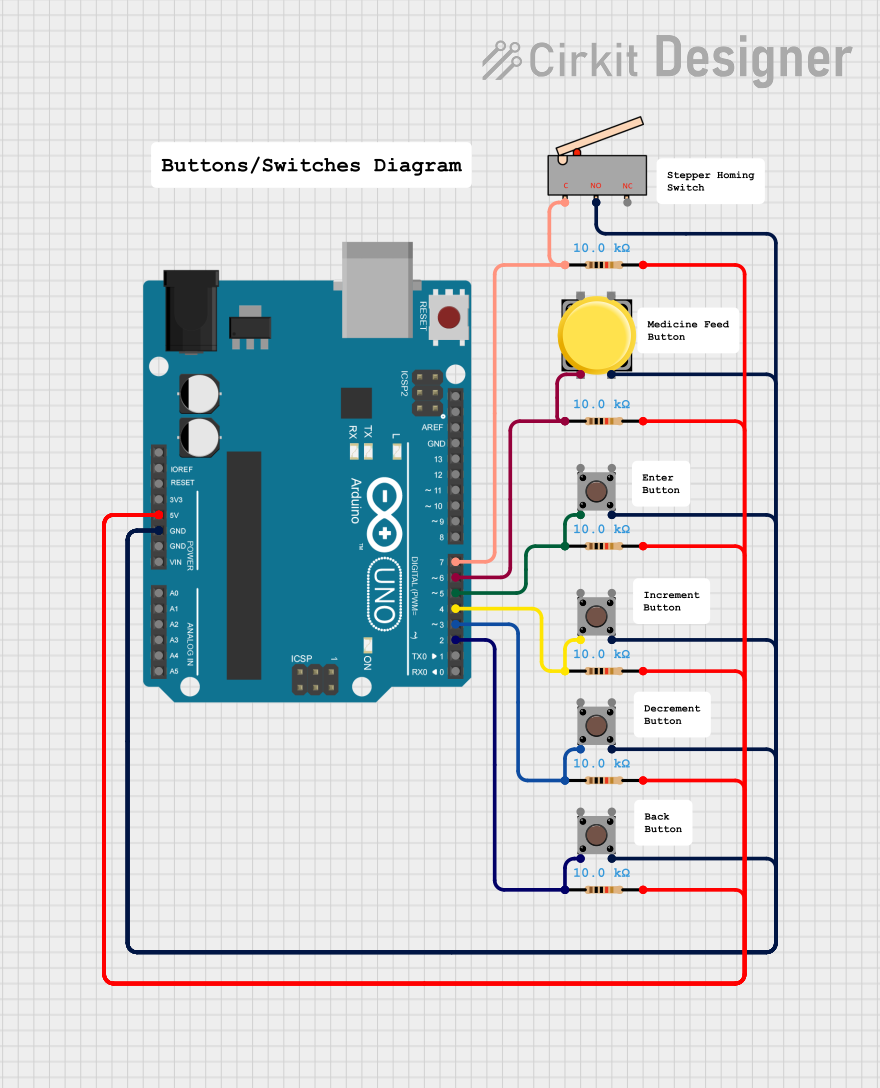

Explore Projects Built with Button Limit Switch
Technical Specifications
Key Technical Details
| Parameter | Value |
|---|---|
| Operating Voltage | 5V to 30V DC |
| Operating Current | 5mA to 10A |
| Contact Resistance | ≤ 50mΩ |
| Insulation Resistance | ≥ 100MΩ |
| Mechanical Life | 1,000,000 cycles |
| Electrical Life | 100,000 cycles |
| Operating Temperature | -25°C to +80°C |
Pin Configuration and Descriptions
| Pin Number | Pin Name | Description |
|---|---|---|
| 1 | COM | Common terminal |
| 2 | NO | Normally Open terminal |
| 3 | NC | Normally Closed terminal |
Usage Instructions
How to Use the Component in a Circuit
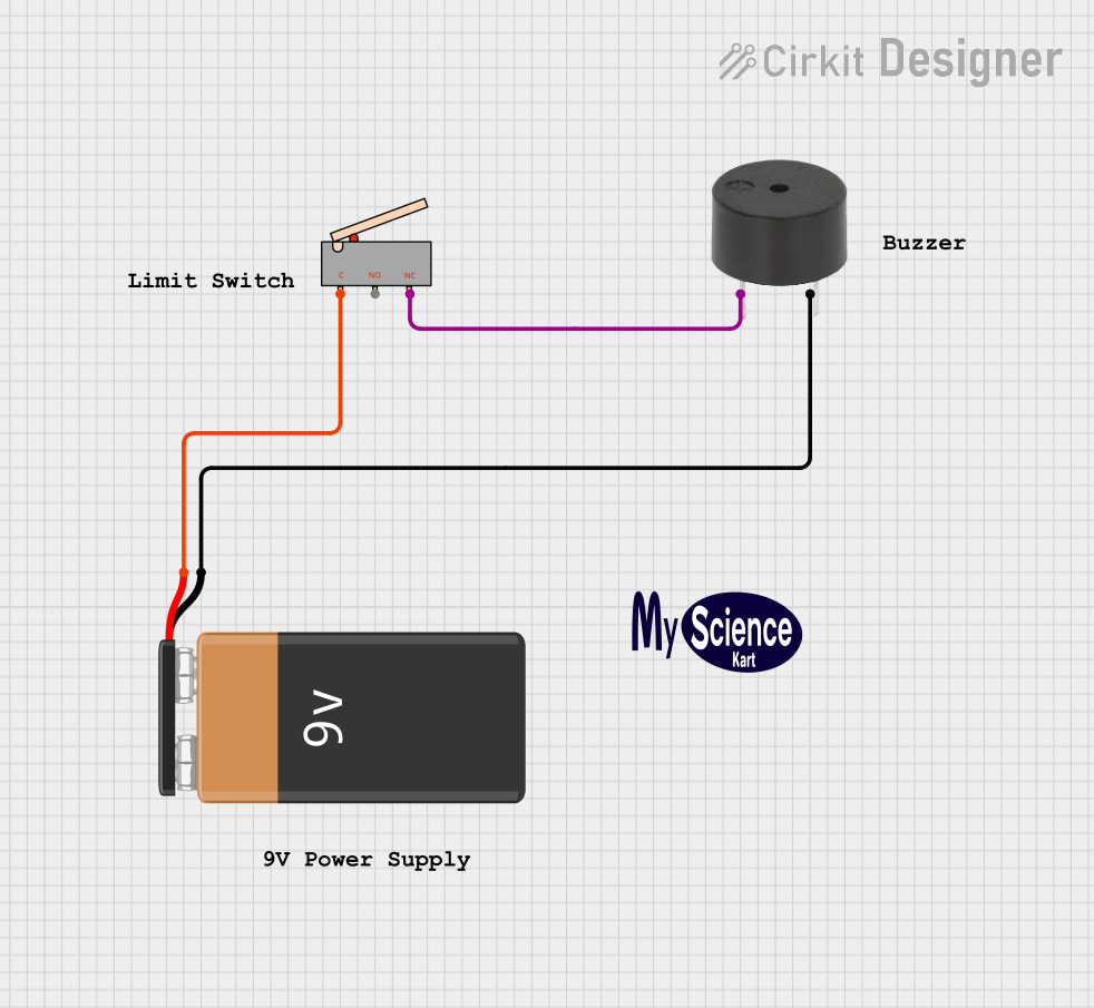
- Identify the Pins: Locate the COM, NO, and NC pins on the Button Limit Switch.
- Connect to Power Source: Connect the COM pin to the ground (GND) of your power source.
- Connect to Load:
- For Normally Open (NO) operation, connect the NO pin to the input of your load.
- For Normally Closed (NC) operation, connect the NC pin to the input of your load.
- Complete the Circuit: Connect the other terminal of your load to the positive voltage supply.
Important Considerations and Best Practices
- Debouncing: Mechanical switches can produce noise or "bounce" when they are actuated. Use a debouncing circuit or software debouncing to ensure reliable operation.
- Current Rating: Ensure that the current passing through the switch does not exceed its rated capacity to avoid damage.
- Mounting: Securely mount the switch to prevent unintended movement or misalignment.
- Environmental Conditions: Consider the operating temperature and environmental conditions to ensure the switch operates reliably.
Example Circuit with Arduino UNO
// Example code to use a Button Limit Switch with Arduino UNO

const int limitSwitchPin = 2; // Pin connected to the limit switch
const int ledPin = 13;        // Pin connected to an LED

void setup() {
  pinMode(limitSwitchPin, INPUT_PULLUP); // Set limit switch pin as input with internal pull-up
  pinMode(ledPin, OUTPUT);               // Set LED pin as output
  Serial.begin(9600);                    // Initialize serial communication
}

void loop() {
  int switchState = digitalRead(limitSwitchPin); // Read the state of the limit switch

  if (switchState == LOW) { // If the switch is pressed
    digitalWrite(ledPin, HIGH); // Turn on the LED
    Serial.println("Limit switch activated!"); // Print message to serial monitor
  } else {
    digitalWrite(ledPin, LOW); // Turn off the LED
  }

  delay(50); // Small delay for debouncing
}
Troubleshooting and FAQs
Common Issues Users Might Face
- Switch Not Activating: Ensure that the switch is properly connected and that the mechanical actuator is making contact.
- Intermittent Operation: This could be due to switch bounce. Implement debouncing techniques in hardware or software.
- No Response from Load: Verify that the load is properly connected and that the switch is functioning correctly by testing with a multimeter.
Solutions and Tips for Troubleshooting
- Check Connections: Ensure all connections are secure and correct.
- Test the Switch: Use a multimeter to check the continuity between COM and NO/NC terminals when the switch is actuated.
- Debouncing: Implement debouncing in your circuit or code to filter out noise from the switch.
FAQs
Q: Can I use the Button Limit Switch with an AC load? A: Yes, but ensure that the switch's voltage and current ratings are suitable for the AC load.
Q: How do I know if the switch is Normally Open or Normally Closed? A: Use a multimeter to check continuity. In the default state, NO will show no continuity, and NC will show continuity.
Q: What is the purpose of the COM pin? A: The COM pin is the common terminal that connects to either the NO or NC terminal depending on the switch's state.
By following this documentation, users should be able to effectively integrate and troubleshoot a Button Limit Switch in their projects.