How to Use Adafruit 9-DOF IMU L3GD20H + LSM303: Examples, Pinouts, and Specs
Introduction
The Adafruit 9-DOF IMU is a compact and versatile inertial measurement unit (IMU) that combines a 3-axis gyroscope (L3GD20H) with a 3-axis accelerometer and magnetometer (LSM303). This sensor is capable of providing nine degrees of freedom (DOF) by measuring linear acceleration, angular rate, and magnetic fields in all three dimensions. It is commonly used in applications such as drone flight control, robotics, motion sensing, and orientation tracking.
Explore Projects Built with Adafruit 9-DOF IMU L3GD20H + LSM303
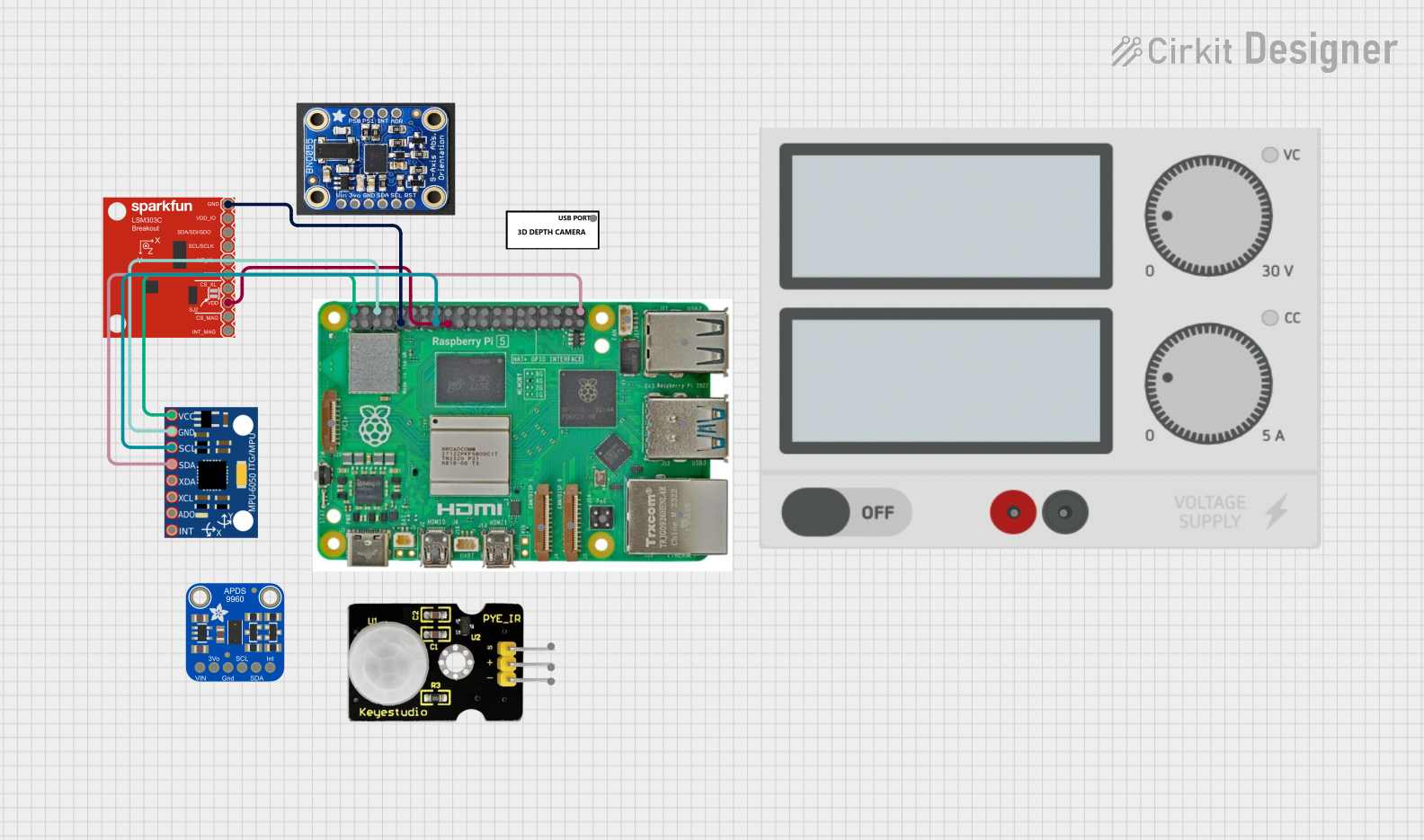


Explore Projects Built with Adafruit 9-DOF IMU L3GD20H + LSM303
Technical Specifications
General Specifications
- Supply Voltage (VDD): 2.16V to 3.6V
- Interface: I2C/SPI (selectable)
- Operating Temperature Range: -40°C to +85°C
L3GD20H Gyroscope Specifications
- Sensitivity: ±245/±500/±2000 dps
- Supply Voltage: 2.2V to 3.6V
- Communication: I2C/SPI
LSM303 Accelerometer and Magnetometer Specifications
- Accelerometer Sensitivity: ±2/±4/±8/±16 g
- Magnetometer Sensitivity: ±1.3/±1.9/±2.5/±4.0/±4.7/±5.6/±8.1 gauss
- Supply Voltage: 2.16V to 3.6V
- Communication: I2C
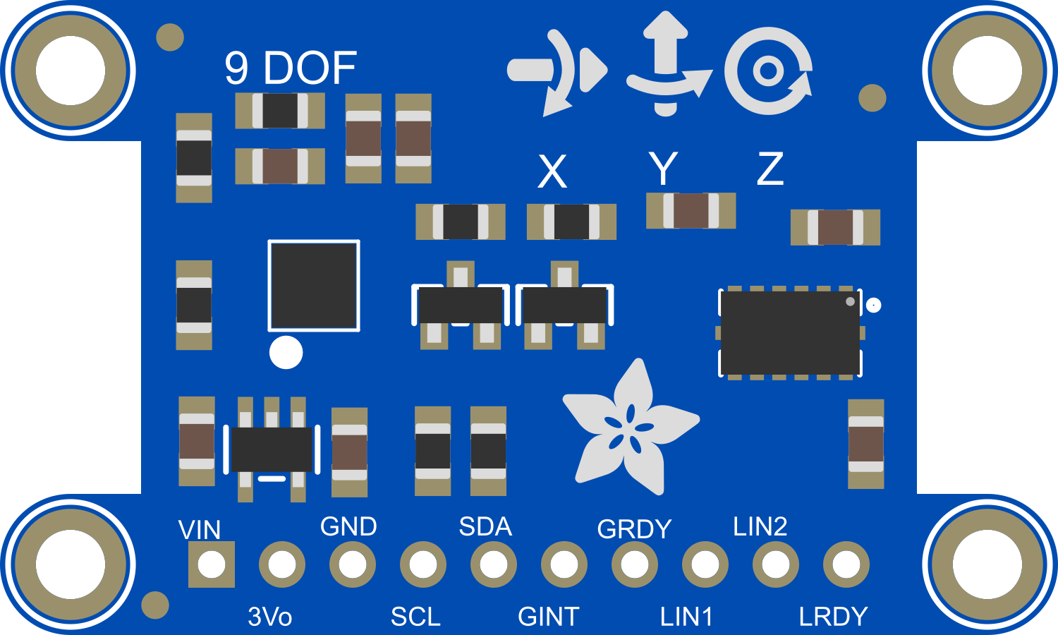
Pin Configuration and Descriptions
| Pin Number | Name | Description |
|---|---|---|
| 1 | VIN | Supply voltage (2.16V to 3.6V) |
| 2 | GND | Ground |
| 3 | SCL | I2C clock / SPI clock |
| 4 | SDA | I2C data / SPI data input (MOSI) |
| 5 | SA0 | I2C address selection / SPI data output (MISO) |
| 6 | SDO | SPI data output for gyroscope / I2C address selection for LSM303 |
| 7 | CS_G | Chip select for gyroscope (active low) |
| 8 | CS_XM | Chip select for accelerometer/magnetometer (active low) |
Usage Instructions
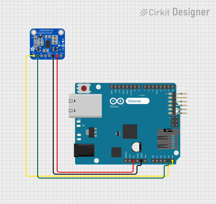
Integration with Arduino
To use the Adafruit 9-DOF IMU with an Arduino UNO, follow these steps:
Connect the IMU pins to the Arduino:
- VIN to 3.3V
- GND to GND
- SCL to A5 (SCL)
- SDA to A4 (SDA)
- SA0 to GND or 3.3V (depending on the desired I2C address)
- CS_G and CS_XM are not used in I2C mode
Install the Adafruit Unified Sensor and 9-DOF libraries using the Arduino Library Manager.
Use the following sample code to read data from the sensor:
#include <Wire.h>
#include <Adafruit_Sensor.h>
#include <Adafruit_L3GD20_U.h>
#include <Adafruit_LSM303_U.h>

/* Assign a unique ID to the sensors */
Adafruit_L3GD20_Unified gyro = Adafruit_L3GD20_Unified(20);
Adafruit_LSM303_Accel_Unified accel = Adafruit_LSM303_Accel_Unified(30);
Adafruit_LSM303_Mag_Unified mag = Adafruit_LSM303_Mag_Unified(40);

void setup(void) {
  Serial.begin(9600);
  if(!gyro.begin() || !accel.begin() || !mag.begin()) {
    /* There was a problem detecting the sensors ... check your connections */
    Serial.println("Ooops, no sensor detected ... Check your wiring!");
    while(1);
  }
}

void loop(void) {
  /* Get a new sensor event */
  sensors_event_t event;

  gyro.getEvent(&event);
  /* Display the results (gyroscope data is in degrees per second) */
  Serial.print("X: "); Serial.print(event.gyro.x); Serial.print(" ");
  Serial.print("Y: "); Serial.print(event.gyro.y); Serial.print(" ");
  Serial.print("Z: "); Serial.print(event.gyro.z); Serial.println(" dps");

  accel.getEvent(&event);
  /* Display the results (acceleration is measured in m/s^2) */
  Serial.print("X: "); Serial.print(event.acceleration.x); Serial.print(" ");
  Serial.print("Y: "); Serial.print(event.acceleration.y); Serial.print(" ");
  Serial.print("Z: "); Serial.print(event.acceleration.z); Serial.println(" m/s^2");

  mag.getEvent(&event);
  /* Display the results (magnetic vector values are in micro-Tesla (uT)) */
  Serial.print("X: "); Serial.print(event.magnetic.x); Serial.print(" ");
  Serial.print("Y: "); Serial.print(event.magnetic.y); Serial.print(" ");
  Serial.print("Z: "); Serial.print(event.magnetic.z); Serial.println(" uT");

  delay(500);
}
Best Practices
- Ensure that the power supply is stable and within the specified voltage range.
- Use pull-up resistors on the I2C lines if multiple devices are connected to the bus.
- Avoid placing the sensor near strong magnetic fields to prevent interference with the magnetometer.
Troubleshooting and FAQs
Common Issues
- Sensor not detected: Check the wiring and ensure that the correct I2C address is being used.
- Inaccurate readings: Calibrate the sensor as per the datasheet instructions, and ensure it's away from magnetic interference.
FAQs
Q: Can I use this sensor with a 5V microcontroller? A: Yes, but ensure that the logic levels are shifted down to 3.3V to avoid damaging the sensor.
Q: How do I change the I2C address? A: The I2C address can be changed by connecting the SA0 pin to either GND or 3.3V.
Q: What is the default I2C address? A: The default I2C address for the L3GD20H is 0x6B and for the LSM303 is 0x1E (accelerometer) and 0x1E (magnetometer) when SA0 is connected to GND.
For further assistance, consult the Adafruit support forums or the sensor datasheets.