How to Use DC_DC12/5cccv: Examples, Pinouts, and Specs
Introduction
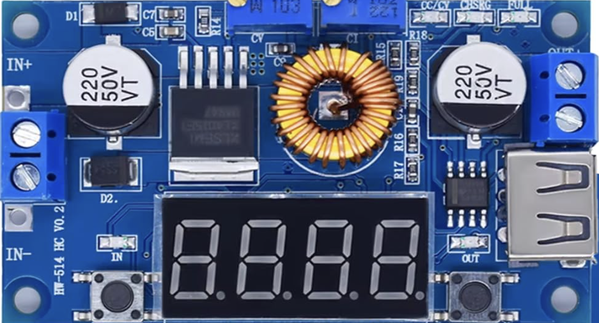
The DC_DC12/5cccv is a DC-DC step-down (buck) converter manufactured by LOWES with the part ID 46789. This component is designed to efficiently convert a 12V DC input to a stable 5V DC output, making it ideal for powering low-voltage devices such as microcontrollers, sensors, and other electronic modules from a higher voltage source. Its compact design and high efficiency make it a popular choice for embedded systems, automotive applications, and portable electronics.
Explore Projects Built with DC_DC12/5cccv


Explore Projects Built with DC_DC12/5cccv
Common Applications
- Powering 5V microcontrollers (e.g., Arduino, Raspberry Pi)
- Supplying power to USB devices from a 12V source
- Automotive electronics (e.g., powering dash cams or GPS units)
- Battery-powered systems requiring voltage regulation
- General-purpose voltage step-down in embedded systems
Technical Specifications
Key Specifications
| Parameter | Value |
|---|---|
| Input Voltage Range | 8V to 14V |
| Output Voltage | 5V (fixed) |
| Output Current | Up to 3A |
| Efficiency | Up to 92% |
| Switching Frequency | 150 kHz |
| Operating Temperature | -40°C to +85°C |
| Dimensions | 25mm x 20mm x 10mm |
| Manufacturer | LOWES |
| Part ID | 46789 |
Pin Configuration
The DC_DC12/5cccv module typically has four pins for input and output connections. The table below describes each pin:
| Pin Number | Pin Name | Description |
|---|---|---|
| 1 | VIN+ | Positive input voltage (8V to 14V) |
| 2 | VIN- | Negative input voltage (ground) |
| 3 | VOUT+ | Positive output voltage (5V) |
| 4 | VOUT- | Negative output voltage (ground) |
Usage Instructions
How to Use the Component in a Circuit
- Connect the Input Voltage:
- Connect the VIN+ pin to the positive terminal of your 12V power source.
- Connect the VIN- pin to the ground terminal of your power source.
- Connect the Output Voltage:
- Connect the VOUT+ pin to the positive terminal of the device you want to power.
- Connect the VOUT- pin to the ground terminal of the device.
- Verify Connections:
- Double-check all connections to ensure proper polarity and avoid short circuits.
- Power On:
- Turn on the 12V power source. The module will regulate the input voltage and provide a stable 5V output.
Important Considerations
- Heat Dissipation: If the module is operating near its maximum current rating (3A), ensure adequate ventilation or attach a heatsink to prevent overheating.
- Input Voltage Range: Do not exceed the specified input voltage range (8V to 14V) to avoid damaging the module.
- Load Requirements: Ensure the connected load does not draw more than 3A to maintain stable operation.
- Polarity Protection: Double-check the polarity of the input and output connections to prevent damage.
Example: Using with an Arduino UNO
The DC_DC12/5cccv can be used to power an Arduino UNO from a 12V battery. Below is an example circuit and Arduino code:
Circuit Connections
- Connect the VIN+ pin of the module to the positive terminal of the 12V battery.
- Connect the VIN- pin of the module to the negative terminal of the 12V battery.
- Connect the VOUT+ pin of the module to the 5V pin of the Arduino UNO.
- Connect the VOUT- pin of the module to the GND pin of the Arduino UNO.
Arduino Code Example
// Example code to blink an LED connected to pin 13 of the Arduino UNO
// Ensure the Arduino is powered via the DC_DC12/5cccv module

void setup() {
  pinMode(13, OUTPUT); // Set pin 13 as an output
}

void loop() {
  digitalWrite(13, HIGH); // Turn the LED on
  delay(1000);            // Wait for 1 second
  digitalWrite(13, LOW);  // Turn the LED off
  delay(1000);            // Wait for 1 second
}
Troubleshooting and FAQs
Common Issues and Solutions
No Output Voltage:
- Cause: Incorrect input connections or insufficient input voltage.
- Solution: Verify that the input voltage is within the 8V to 14V range and that the polarity is correct.
Overheating:
- Cause: Excessive current draw or poor ventilation.
- Solution: Reduce the load current or improve heat dissipation by adding a heatsink or fan.
Output Voltage Fluctuations:
- Cause: Load exceeds the maximum current rating or unstable input voltage.
- Solution: Ensure the load current is below 3A and use a stable power source.
Module Not Working After Connection:
- Cause: Reverse polarity or input voltage exceeds the maximum rating.
- Solution: Check and correct the polarity. Replace the module if it has been damaged.
FAQs
Q1: Can I use this module to power a Raspberry Pi?
A1: Yes, the module can power a Raspberry Pi as long as the total current draw does not exceed 3A.
Q2: Is the output voltage adjustable?
A2: No, the output voltage is fixed at 5V.
Q3: Can I use this module with a 24V input?
A3: No, the input voltage range is limited to 8V to 14V. Using a 24V input will damage the module.
Q4: Does the module have built-in short-circuit protection?
A4: Yes, the module includes basic short-circuit protection, but it is recommended to avoid intentional short circuits.
This concludes the documentation for the DC_DC12/5cccv. For further assistance, refer to the manufacturer's datasheet or contact LOWES support.