
How to Use Motorola XPR7550e: Examples, Pinouts, and Specs
 Design with Motorola XPR7550e in Cirkit Designer
Introduction
The Motorola XPR7550e is a professional-grade digital two-way radio designed for reliable communication in demanding environments. Its accessory port is a critical interface that allows users to connect external devices such as headsets, microphones, programming cables, and other peripherals. This port enhances the functionality of the radio by enabling seamless integration with additional hardware.
Explore Projects Built with Motorola XPR7550e
 Open Project in Cirkit Designer
 Open Project in Cirkit Designer
 Open Project in Cirkit Designer
 Open Project in Cirkit Designer
Explore Projects Built with Motorola XPR7550e
Open Project in Cirkit DesignerOpen Project in Cirkit DesignerOpen Project in Cirkit DesignerOpen Project in Cirkit DesignerCommon Applications and Use Cases
- Connecting external audio devices (e.g., headsets, remote speaker microphones)
- Programming and configuring the radio via a PC
- Integrating with push-to-talk (PTT) accessories
- Connecting Bluetooth adapters or other specialized peripherals
- Enabling hands-free communication in industrial or field environments
Technical Specifications
Key Technical Details
- Port Type: Multi-pin accessory connector
- Compatibility: Motorola XPR7550e and compatible accessories
- Voltage Levels: 3.3V logic for data communication
- Current Rating: Supports low-power external devices
- Durability: Ruggedized design to withstand harsh environments
- Sealing: IP68-rated when properly connected with compatible accessories
Pin Configuration and Descriptions
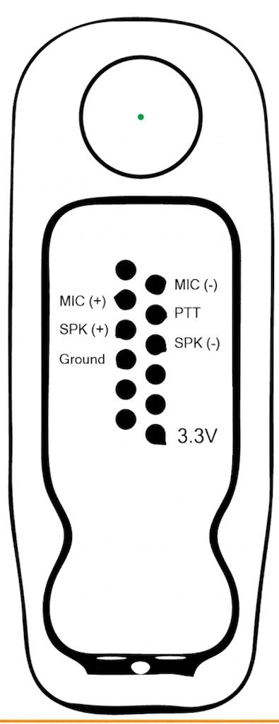
The accessory port on the Motorola XPR7550e features a multi-pin connector. Below is the pinout and description of each pin:
| Pin Number | Name | Description |
|---|---|---|
| 1 | Ground (GND) | Common ground for all signals and power. |
| 2 | Microphone Input | Input for external microphone audio signals. |
| 3 | Speaker Output | Output for external speaker audio signals. |
| 4 | PTT (Push-to-Talk) | Activates the transmitter when connected to a PTT accessory. |
| 5 | Data TX | Transmit data line for programming or communication with external devices. |
| 6 | Data RX | Receive data line for programming or communication with external devices. |
| 7 | Accessory Detect | Detects the presence of a connected accessory. |
| 8 | Power Supply | Provides power to external accessories (voltage and current depend on the device). |
Note: Always refer to the official Motorola documentation for detailed electrical characteristics and compatibility information.
Usage Instructions
How to Use the Accessory Port in a Circuit
Connecting Accessories:
- Ensure the radio is powered off before connecting any accessory to the port.
- Align the accessory connector with the port and secure it firmly to ensure a proper connection.
- Power on the radio and verify that the accessory is detected (if applicable).
Programming the Radio:
- Use a Motorola-compatible programming cable to connect the accessory port to a PC.
- Install the required Motorola programming software (e.g., CPS).
- Follow the software instructions to configure the radio settings.
Using External Audio Devices:
- Connect a compatible headset or microphone to the accessory port.
- Adjust the radio's audio settings to optimize performance with the connected device.
Important Considerations and Best Practices
- Compatibility: Always use Motorola-approved accessories to ensure proper functionality and avoid damage to the radio.
- Sealing: Ensure the accessory connector is properly sealed to maintain the radio's IP68 rating.
- Power Supply: Avoid connecting high-power devices directly to the accessory port, as it is designed for low-power peripherals.
- Cable Management: Use strain relief or cable clips to prevent accidental disconnection or damage to the port.
Example: Using the Accessory Port with an Arduino UNO
The accessory port can be used to interface the XPR7550e with an Arduino UNO for data communication. Below is an example of how to send and receive data using the port:
#include <SoftwareSerial.h>

// Define RX and TX pins for communication with the XPR7550e
#define RX_PIN 10  // Arduino pin connected to Data TX (Pin 5 of accessory port)
#define TX_PIN 11  // Arduino pin connected to Data RX (Pin 6 of accessory port)

SoftwareSerial xpr7550eSerial(RX_PIN, TX_PIN);

void setup() {
  // Initialize serial communication with the XPR7550e
  xpr7550eSerial.begin(9600); // Set baud rate to match the radio's configuration
  Serial.begin(9600);         // For debugging via the Arduino Serial Monitor

  Serial.println("XPR7550e Communication Initialized");
}

void loop() {
  // Check if data is available from the XPR7550e
  if (xpr7550eSerial.available()) {
    String receivedData = xpr7550eSerial.readString();
    Serial.print("Received from XPR7550e: ");
    Serial.println(receivedData);
  }

  // Example: Send a test message to the XPR7550e
  if (Serial.available()) {
    String message = Serial.readString();
    xpr7550eSerial.println(message);
    Serial.println("Message sent to XPR7550e");
  }
}
Note: Ensure proper voltage level shifting if the Arduino operates at 5V logic, as the XPR7550e uses 3.3V logic.
Troubleshooting and FAQs
Common Issues Users Might Face
Accessory Not Detected:
- Ensure the accessory is compatible with the XPR7550e.
- Check for a secure connection and clean the port if necessary.
Audio Quality Issues:
- Verify that the connected audio device is functioning properly.
- Adjust the radio's audio settings to match the accessory specifications.
Programming Cable Not Working:
- Confirm that the correct drivers and programming software are installed on the PC.
- Check the cable for physical damage or loose connections.
Data Communication Problems:
- Ensure the baud rate and communication settings match between the radio and the external device.
- Use proper voltage level shifting if interfacing with devices operating at different logic levels.
Solutions and Tips for Troubleshooting
- Inspect the Port: Regularly check the accessory port for dirt, debris, or damage.
- Use Genuine Accessories: Non-Motorola accessories may not function correctly or could damage the radio.
- Reset the Radio: If issues persist, try resetting the radio to its factory settings.
- Consult the Manual: Refer to the official Motorola XPR7550e user manual for detailed troubleshooting steps.
By following this documentation, users can effectively utilize the Motorola XPR7550e accessory port for a wide range of applications, ensuring reliable and efficient communication.