
How to Use Screw terminal - 2 pins: Examples, Pinouts, and Specs
 Design with Screw terminal - 2 pins in Cirkit Designer
Introduction
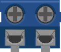
A screw terminal with two pins is a simple yet versatile component used for creating secure and reliable electrical connections. It allows wires to be easily attached or detached by tightening or loosening screws, making it ideal for applications where frequent reconfiguration or maintenance is required. This component is commonly used in prototyping, industrial control systems, power distribution, and DIY electronics projects.
Explore Projects Built with Screw terminal - 2 pins
 Open Project in Cirkit Designer
 Open Project in Cirkit Designer
 Open Project in Cirkit Designer
 Open Project in Cirkit Designer
Explore Projects Built with Screw terminal - 2 pins
Open Project in Cirkit DesignerOpen Project in Cirkit DesignerOpen Project in Cirkit DesignerOpen Project in Cirkit DesignerCommon Applications and Use Cases
- Connecting wires in prototyping and breadboard setups
- Power distribution in low-voltage circuits
- Industrial control systems and automation
- DIY electronics projects requiring modular connections
- Secure connections for sensors, motors, or other peripherals
Technical Specifications
The screw terminal - 2 pins is designed to provide a robust and reusable connection for low to medium current applications. Below are its key specifications:
| Parameter | Value |
|---|---|
| Number of Pins | 2 |
| Rated Voltage | 300V AC/DC (varies by model) |
| Rated Current | 10A (typical, check model specs) |
| Wire Gauge Support | 26 AWG to 14 AWG |
| Terminal Material | Brass or copper alloy (tin-plated) |
| Insulation Material | Polyamide (PA66) or equivalent |
| Mounting Type | PCB through-hole or panel mount |
| Screw Type | M2 or M3 (varies by model) |
| Operating Temperature | -40°C to +105°C |
Pin Configuration and Descriptions
The screw terminal has two pins that connect to a PCB or other mounting surface. Below is the pin configuration:
| Pin Number | Description |
|---|---|
| 1 | Electrical connection for wire 1 |
| 2 | Electrical connection for wire 2 |
Usage Instructions
How to Use the Component in a Circuit
Mounting the Terminal:
- If using a PCB, solder the two pins of the terminal into the designated through-hole pads.
- For panel mounting, secure the terminal using screws or clips as per the design.
Connecting Wires:
- Strip the insulation from the wire ends (approximately 5-7 mm).
- Insert the stripped wire into the terminal opening.
- Tighten the screw firmly to secure the wire. Avoid overtightening to prevent damage to the wire or terminal.
Testing the Connection:
- Gently tug on the wire to ensure it is securely fastened.
- Verify the electrical connection using a multimeter.
Important Considerations and Best Practices
- Ensure the wire gauge is compatible with the terminal's specifications.
- Avoid overtightening screws, as this can damage the wire or strip the screw threads.
- Use insulated wires to prevent accidental short circuits.
- For high-current applications, verify the terminal's current rating and ensure proper heat dissipation.
- If used in a high-vibration environment, periodically check the screws for tightness.
Example: Connecting to an Arduino UNO
While the screw terminal itself does not directly interface with an Arduino, it can be used to connect peripherals like sensors or motors to the Arduino. Below is an example of using a screw terminal to connect a DC motor to an Arduino UNO via a motor driver:
// Example: Controlling a DC motor connected via a screw terminal
// Components: Arduino UNO, motor driver, DC motor, screw terminal

const int motorPin = 9; // PWM pin connected to motor driver

void setup() {
  pinMode(motorPin, OUTPUT); // Set motor pin as output
}

void loop() {
  analogWrite(motorPin, 128); // Run motor at 50% speed
  delay(2000);               // Wait for 2 seconds
  analogWrite(motorPin, 0);   // Stop motor
  delay(2000);               // Wait for 2 seconds
}
Note: Ensure the motor driver is properly connected to the Arduino and the screw terminal is used to securely attach the motor wires.
Troubleshooting and FAQs
Common Issues Users Might Face
Loose Connections:
- Cause: Screws not tightened properly.
- Solution: Ensure screws are firmly tightened without overtightening.
Wire Slipping Out:
- Cause: Insufficient wire stripping or improper insertion.
- Solution: Strip the wire to the recommended length and insert it fully before tightening.
Overheating:
- Cause: Exceeding the terminal's current rating.
- Solution: Verify the current requirements of your circuit and ensure the terminal is rated for the load.
Damaged Screws or Threads:
- Cause: Overtightening or using incompatible tools.
- Solution: Use the correct screwdriver size and avoid excessive force.
FAQs
Q1: Can I use this terminal for high-voltage applications?
A1: The terminal is typically rated for up to 300V AC/DC. Always check the specific model's voltage rating before use.
Q2: What type of screwdriver should I use?
A2: Use a flathead or Phillips screwdriver that matches the screw size (e.g., M2 or M3).
Q3: Can I use stranded wires with this terminal?
A3: Yes, stranded wires are compatible. For best results, twist the strands together before inserting them into the terminal.
Q4: How do I prevent corrosion on the terminal?
A4: Use terminals with tin-plated contacts and avoid exposure to moisture. For added protection, apply a thin layer of dielectric grease.
By following these guidelines, you can ensure reliable and long-lasting connections using the screw terminal - 2 pins.