How to Use C1815: Examples, Pinouts, and Specs
Introduction
The C1815 is a general-purpose NPN bipolar junction transistor (BJT) designed for amplification and switching applications. Manufactured by Transistor, this component is widely used in low to medium power circuits due to its reliable performance and compact size. With a maximum collector current of 800 mA and a maximum collector-emitter voltage of 50 V, the C1815 is suitable for a variety of applications, including audio amplification, signal processing, and low-power switching.
Explore Projects Built with C1815


Explore Projects Built with C1815
Common Applications
- Audio signal amplification
- Low-power switching circuits
- Oscillator circuits
- General-purpose signal processing
- Small motor control
Technical Specifications
Below are the key technical details of the C1815 transistor:
| Parameter | Value |
|---|---|
| Transistor Type | NPN |
| Maximum Collector Current (Ic) | 800 mA |
| Maximum Collector-Emitter Voltage (Vce) | 50 V |
| Maximum Collector-Base Voltage (Vcb) | 60 V |
| Maximum Emitter-Base Voltage (Veb) | 5 V |
| DC Current Gain (hFE) | 70 to 700 (varies by model) |
| Power Dissipation (Pc) | 400 mW |
| Transition Frequency (ft) | 80 MHz |
| Package Type | TO-92 |
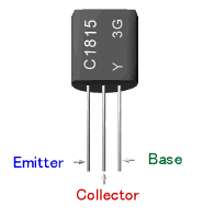
Pin Configuration
The C1815 transistor comes in a TO-92 package with three pins. The pinout is as follows:
| Pin Number | Pin Name | Description |
|---|---|---|
| 1 | Emitter (E) | Current flows out of this pin. |
| 2 | Base (B) | Controls the transistor's operation. |
| 3 | Collector (C) | Current flows into this pin. |
The pin configuration is typically viewed with the flat side of the TO-92 package facing you.
Usage Instructions
Using the C1815 in a Circuit
The C1815 transistor can be used in two primary modes: as a switch or as an amplifier.
1. Switching Mode
In switching mode, the transistor operates as a digital on/off switch. To turn the transistor on, apply a small current to the base pin. This allows a larger current to flow from the collector to the emitter.
2. Amplification Mode
In amplification mode, the transistor amplifies a small input signal at the base to produce a larger output signal at the collector. The gain of the transistor (hFE) determines the amplification factor.
Example Circuit: LED Control with Arduino UNO
The C1815 can be used to control an LED with an Arduino UNO. Below is an example circuit and code:
Circuit Setup:
- Connect the emitter (E) to ground.
- Connect the collector (C) to one terminal of the LED (with a current-limiting resistor in series).
- Connect the other terminal of the LED to the positive supply voltage (e.g., 5V).
- Connect the base (B) to an Arduino digital pin through a 1 kΩ resistor.
Arduino Code:
// Define the pin connected to the transistor base
const int transistorBasePin = 9;

void setup() {
  // Set the transistor base pin as an output
  pinMode(transistorBasePin, OUTPUT);
}

void loop() {
  // Turn the LED on by sending a HIGH signal to the transistor base
  digitalWrite(transistorBasePin, HIGH);
  delay(1000); // Keep the LED on for 1 second

  // Turn the LED off by sending a LOW signal to the transistor base
  digitalWrite(transistorBasePin, LOW);
  delay(1000); // Keep the LED off for 1 second
}
Important Considerations
- Always use a base resistor (typically 1 kΩ to 10 kΩ) to limit the base current and protect the transistor.
- Ensure the collector current does not exceed 800 mA to avoid damaging the transistor.
- Use a heat sink if the transistor is operating near its maximum power dissipation (400 mW).
Troubleshooting and FAQs
Common Issues
Transistor Not Switching Properly
- Cause: Insufficient base current.
- Solution: Check the base resistor value and ensure the base current is sufficient to saturate the transistor.
Overheating
- Cause: Exceeding the maximum power dissipation or collector current.
- Solution: Reduce the load current or use a heat sink.
No Output Signal
- Cause: Incorrect pin connections or damaged transistor.
- Solution: Verify the pin connections and replace the transistor if necessary.
Low Amplification
- Cause: Low hFE or insufficient input signal.
- Solution: Check the transistor's hFE and ensure the input signal is within the required range.
FAQs
Q: Can the C1815 be used for high-power applications?
A: No, the C1815 is designed for low to medium power applications with a maximum collector current of 800 mA and power dissipation of 400 mW.
Q: What is the typical base resistor value for the C1815?
A: A base resistor between 1 kΩ and 10 kΩ is typically used, depending on the required base current.
Q: Can the C1815 be used in RF circuits?
A: Yes, the C1815 has a transition frequency (ft) of 80 MHz, making it suitable for low-frequency RF applications.
Q: How do I identify the pins on the C1815?
A: With the flat side of the TO-92 package facing you, the pins from left to right are Emitter (E), Base (B), and Collector (C).