How to Use Female DC Jack Connector: Examples, Pinouts, and Specs
Introduction
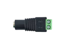
The Female DC Jack Connector is a socket designed to receive a DC power plug, enabling a secure and reliable connection for powering electronic devices. It is widely used in consumer electronics, DIY projects, and prototyping to provide a convenient interface for connecting external power supplies. This component is particularly valued for its ease of use, durability, and compatibility with a variety of DC power plugs.
Explore Projects Built with Female DC Jack Connector


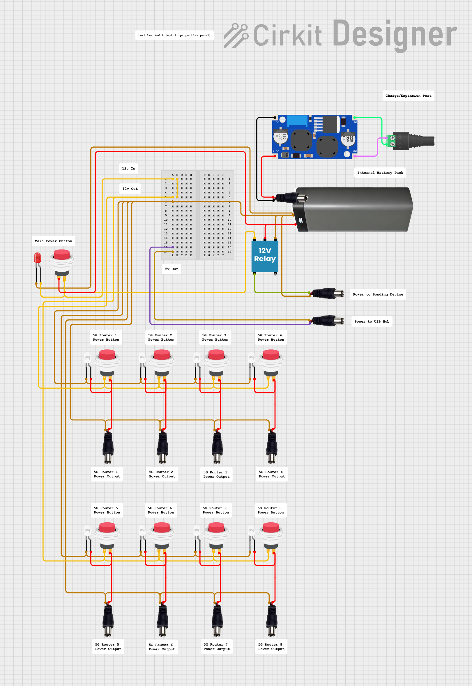
Explore Projects Built with Female DC Jack Connector
Common Applications and Use Cases
- Powering Arduino boards, Raspberry Pi, and other microcontrollers
- Consumer electronics such as radios, routers, and LED lighting systems
- DIY electronics projects and prototyping
- Battery-powered devices with external charging options
- Robotics and small motorized systems
Technical Specifications
The Female DC Jack Connector is available in various sizes, with the most common being 5.5mm outer diameter and 2.1mm or 2.5mm inner diameter. Below are the general specifications:
| Parameter | Value |
|---|---|
| Voltage Rating | Typically 12V to 24V (varies by model) |
| Current Rating | 1A to 5A (depending on the model) |
| Connector Size | Commonly 5.5mm OD, 2.1mm or 2.5mm ID |
| Mounting Style | Panel mount or PCB mount |
| Material | Plastic housing with metal contacts |
| Polarity | Center pin positive (most common) |
Pin Configuration and Descriptions
The Female DC Jack Connector typically has three pins:
| Pin | Description |
|---|---|
| Pin 1 | Positive terminal (center pin) - connects to the positive voltage of the power supply. |
| Pin 2 | Negative terminal (outer sleeve) - connects to the ground of the power supply. |
| Pin 3 | Switch pin (optional) - disconnects internal power when a plug is inserted. |
Note: The switch pin is present in some models and is used to toggle between internal and external power sources.
Usage Instructions
How to Use the Female DC Jack Connector in a Circuit
- Identify the Pins: Use the pin configuration table above to identify the positive, negative, and switch pins (if applicable).
- Soldering:
- For panel-mount connectors, solder wires to the pins, ensuring proper polarity.
- For PCB-mount connectors, solder the pins directly to the PCB pads.
- Polarity Check: Verify the polarity of the DC power plug to ensure it matches the connector's configuration (center positive is standard).
- Mounting: Secure the connector to the panel or PCB using screws or solder joints, as applicable.
- Connect Power: Insert the DC power plug into the jack to establish a connection.
Important Considerations and Best Practices
- Polarity: Always confirm the polarity of the power supply and connector to avoid damage to the circuit.
- Current Rating: Ensure the connector's current rating matches or exceeds the requirements of your device.
- Secure Mounting: For panel-mount connectors, use a nut or washer to prevent loosening during operation.
- Switch Pin Usage: If using a model with a switch pin, connect it to toggle between internal and external power sources.
Example: Connecting to an Arduino UNO
The Female DC Jack Connector can be used to power an Arduino UNO with an external 9V or 12V DC adapter. Below is an example of how to connect it:
- Solder the positive pin of the connector to the VIN pin of the Arduino.
- Solder the negative pin of the connector to the GND pin of the Arduino.
- Insert the DC power plug into the jack to power the Arduino.
Arduino Code Example
If you are using the Female DC Jack Connector to power an Arduino UNO, no specific code is required for power management. However, here is a simple sketch to verify that the Arduino is powered and functioning:
// Simple LED Blink Test
// This code blinks the onboard LED to confirm the Arduino is powered.

void setup() {
  pinMode(LED_BUILTIN, OUTPUT); // Set the onboard LED pin as an output
}

void loop() {
  digitalWrite(LED_BUILTIN, HIGH); // Turn the LED on
  delay(1000);                     // Wait for 1 second
  digitalWrite(LED_BUILTIN, LOW);  // Turn the LED off
  delay(1000);                     // Wait for 1 second
}
Troubleshooting and FAQs
Common Issues and Solutions
No Power to the Circuit
- Cause: Incorrect polarity or loose connections.
- Solution: Verify the polarity of the power supply and ensure all connections are secure.
Overheating Connector
- Cause: Exceeding the current rating of the connector.
- Solution: Use a connector with a higher current rating or reduce the load on the circuit.
Intermittent Power
- Cause: Loose or damaged DC plug or jack.
- Solution: Inspect the plug and jack for wear or damage and replace if necessary.
Switch Pin Not Working
- Cause: Incorrect wiring of the switch pin.
- Solution: Verify the wiring and ensure the switch pin is connected correctly.
FAQs
Q: Can I use the Female DC Jack Connector with a 5V power supply?
A: Yes, as long as the voltage and current ratings of the connector match the requirements of your circuit.
Q: How do I determine the polarity of my DC power plug?
A: Most DC power plugs have a diagram indicating polarity. The center pin is usually positive, and the outer sleeve is negative.
Q: Can I use the switch pin to control a relay?
A: Yes, the switch pin can be used to toggle a relay or other components, provided the current and voltage ratings are not exceeded.
Q: Is the connector waterproof?
A: Standard Female DC Jack Connectors are not waterproof. Use a waterproof model for outdoor or moisture-prone environments.