How to Use Differential Servo Encoder Converter (A, B) for PLC TTL/NPN: Examples, Pinouts, and Specs
Introduction
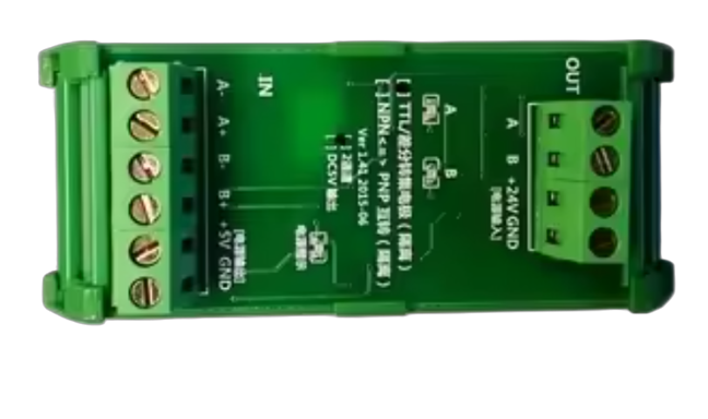
The Differential Servo Encoder Converter (A, B) for PLC TTL/NPN is a versatile device designed to convert differential signals from a servo encoder into a format compatible with Programmable Logic Controllers (PLCs). It supports TTL or NPN output, ensuring reliable digital communication in industrial automation systems. This component is commonly used in motion control, robotics, and industrial machinery where precise position or speed feedback is required.
Explore Projects Built with Differential Servo Encoder Converter (A, B) for PLC TTL/NPN


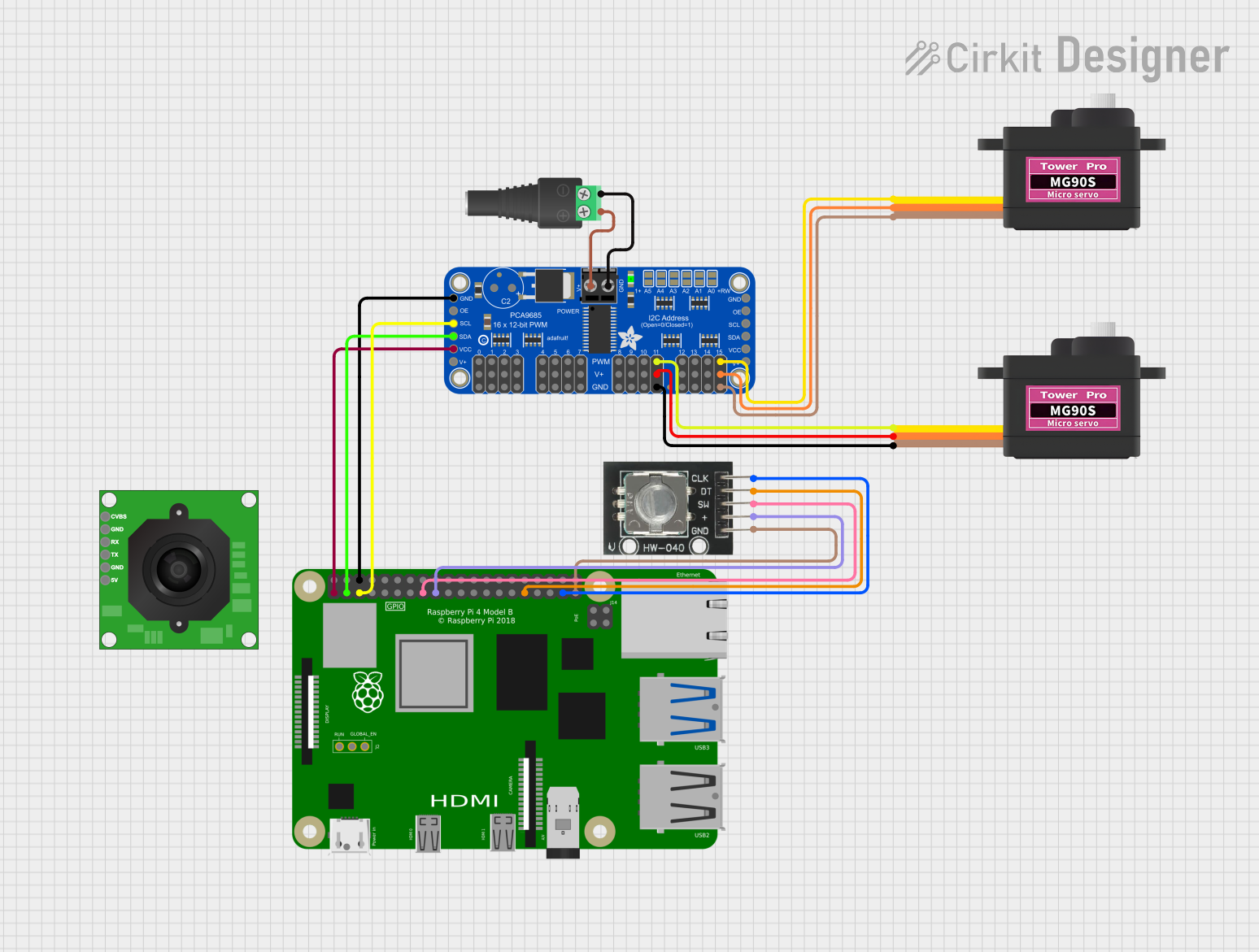
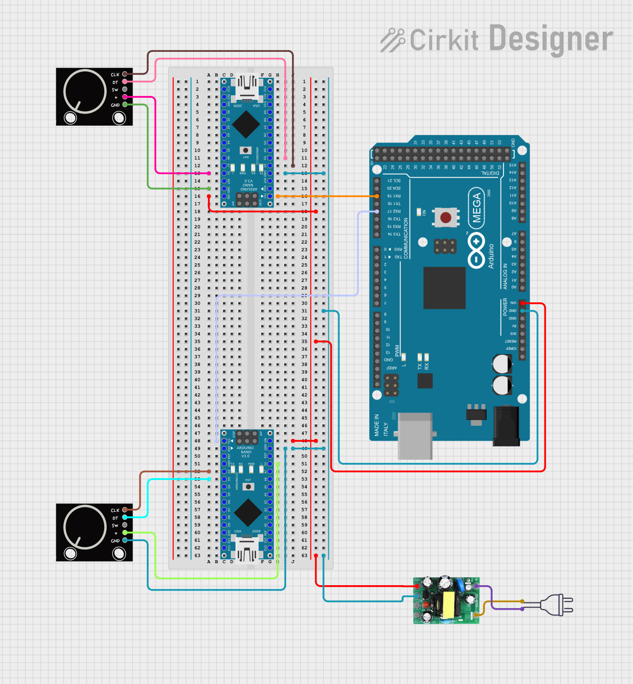
Explore Projects Built with Differential Servo Encoder Converter (A, B) for PLC TTL/NPN
Common Applications and Use Cases
- Motion control systems in industrial automation
- Robotics for position and speed feedback
- CNC machines and servo motor control
- PLC-based monitoring and control systems
- Signal conversion for long-distance transmission
Technical Specifications
Below are the key technical details of the Differential Servo Encoder Converter:
| Parameter | Specification |
|---|---|
| Input Signal Type | Differential (A, B) |
| Output Signal Type | TTL or NPN |
| Input Voltage Range | 5V to 24V DC |
| Output Voltage Range | 5V to 24V DC (matches input voltage) |
| Maximum Output Current | 20mA per channel |
| Operating Temperature Range | -20°C to 70°C |
| Signal Frequency Range | Up to 200 kHz |
| Isolation | Optically isolated output |
| Dimensions | 50mm x 30mm x 15mm |
Pin Configuration and Descriptions
The pin configuration for the Differential Servo Encoder Converter is as follows:
Input Side (Differential Encoder Signals)
| Pin | Label | Description |
|---|---|---|
| 1 | A+ | Differential encoder signal A+ |
| 2 | A- | Differential encoder signal A- |
| 3 | B+ | Differential encoder signal B+ |
| 4 | B- | Differential encoder signal B- |
| 5 | GND | Ground reference for input signals |
Output Side (PLC-Compatible Signals)
| Pin | Label | Description |
|---|---|---|
| 1 | A | TTL/NPN output signal A |
| 2 | B | TTL/NPN output signal B |
| 3 | GND | Ground reference for output signals |
| 4 | VCC | Power supply for output signals (5-24V) |
Usage Instructions
How to Use the Component in a Circuit
- Power the Converter: Connect the VCC and GND pins on the output side to a DC power supply (5V to 24V).
- Connect the Encoder: Attach the differential encoder signals (A+, A-, B+, B-) to the corresponding input pins on the converter.
- Connect to PLC: Connect the TTL or NPN output signals (A, B) to the PLC's digital input terminals. Ensure the PLC is configured to accept the appropriate signal type.
- Verify Connections: Double-check all connections to ensure proper wiring and polarity.
- Test the System: Power on the system and verify that the PLC receives accurate signals corresponding to the encoder's movement.
Important Considerations and Best Practices
- Ensure the input voltage matches the encoder's specifications to avoid damage.
- Use shielded cables for the encoder signals to minimize noise and interference.
- Maintain proper grounding to ensure signal integrity and prevent ground loops.
- If using long cables, consider adding termination resistors to the differential signal lines to reduce reflections.
- Verify the PLC's input configuration (TTL or NPN) and match it with the converter's output.
Example Code for Arduino UNO
If you are using the Differential Servo Encoder Converter with an Arduino UNO for testing or prototyping, the following code demonstrates how to read the A and B signals:
// Define the input pins for the encoder signals
const int encoderPinA = 2; // Connect to output signal A from the converter
const int encoderPinB = 3; // Connect to output signal B from the converter

volatile int encoderPosition = 0; // Variable to store the encoder position
int lastEncoded = 0; // Variable to store the last encoder state

void setup() {
  pinMode(encoderPinA, INPUT); // Set pin A as input
  pinMode(encoderPinB, INPUT); // Set pin B as input

  // Enable pull-up resistors for noise immunity
  digitalWrite(encoderPinA, HIGH);
  digitalWrite(encoderPinB, HIGH);

  // Attach interrupts to the encoder pins
  attachInterrupt(digitalPinToInterrupt(encoderPinA), updateEncoder, CHANGE);
  attachInterrupt(digitalPinToInterrupt(encoderPinB), updateEncoder, CHANGE);

  Serial.begin(9600); // Initialize serial communication for debugging
}

void loop() {
  // Print the encoder position to the serial monitor
  Serial.println(encoderPosition);
  delay(100); // Delay for readability
}

void updateEncoder() {
  // Read the current state of the encoder pins
  int MSB = digitalRead(encoderPinA); // Most Significant Bit
  int LSB = digitalRead(encoderPinB); // Least Significant Bit

  int encoded = (MSB << 1) | LSB; // Combine the two bits into a single value
  int sum = (lastEncoded << 2) | encoded; // Combine with the last state

  // Determine the direction of rotation
  if (sum == 0b1101 || sum == 0b0100 || sum == 0b0010 || sum == 0b1011) {
    encoderPosition++;
  } else if (sum == 0b1110 || sum == 0b0111 || sum == 0b0001 || sum == 0b1000) {
    encoderPosition--;
  }

  lastEncoded = encoded; // Update the last state
}
Troubleshooting and FAQs
Common Issues Users Might Face
No Output Signal:
- Cause: Incorrect wiring or insufficient power supply.
- Solution: Verify all connections and ensure the power supply voltage is within the specified range.
PLC Not Detecting Signals:
- Cause: Mismatch between the converter's output type (TTL/NPN) and the PLC's input configuration.
- Solution: Check the PLC's input settings and ensure they match the converter's output type.
Noisy or Unstable Signals:
- Cause: Electromagnetic interference or improper grounding.
- Solution: Use shielded cables, ensure proper grounding, and minimize cable length.
Incorrect Position Feedback:
- Cause: Encoder signals not properly connected or termination resistors missing.
- Solution: Verify the encoder connections and add termination resistors if necessary.
Solutions and Tips for Troubleshooting
- Use an oscilloscope to verify the input and output signals for proper waveform and timing.
- Ensure the encoder and converter share a common ground with the PLC.
- If the system operates in a high-noise environment, consider using additional filtering or isolation techniques.
By following this documentation, users can effectively integrate the Differential Servo Encoder Converter into their systems for reliable and accurate signal conversion.