How to Use DRV8833: Examples, Pinouts, and Specs
Introduction
The DRV8833 is a dual H-bridge motor driver designed to control the direction and speed of DC motors and stepper motors. It is a compact and efficient solution for driving motors in robotics, automation, and other motor control applications. With a supply voltage range of 2.7V to 10.8V and the ability to deliver up to 1.5A per channel, the DRV8833 is ideal for low- to medium-power motor control tasks. Its small size and versatile features make it a popular choice for hobbyists and professionals alike.
Explore Projects Built with DRV8833
Explore Projects Built with DRV8833
Common Applications
- Robotics (e.g., controlling wheels or arms)
- Automation systems
- Small conveyor belts
- Remote-controlled vehicles
- Stepper motor control for 3D printers or CNC machines
Technical Specifications
Key Technical Details
- Supply Voltage (VCC): 2.7V to 10.8V
- Output Current (per channel): Up to 1.5A (continuous)
- Peak Current (per channel): 2A (for short durations)
- Control Logic Voltage: 1.8V to 7V
- PWM Frequency: Up to 250 kHz
- Thermal Shutdown Protection: Yes
- Overcurrent Protection: Yes
- Operating Temperature Range: -40°C to 85°C
- Package Type: HTSSOP (16-pin)
Pin Configuration and Descriptions
The DRV8833 has 16 pins, with the following configuration:
| Pin Number | Pin Name | Description |
|---|---|---|
| 1 | AOUT1 | Output 1 for H-bridge A |
| 2 | AOUT2 | Output 2 for H-bridge A |
| 3 | VM | Motor power supply (2.7V to 10.8V) |
| 4 | GND | Ground connection |
| 5 | BOUT1 | Output 1 for H-bridge B |
| 6 | BOUT2 | Output 2 for H-bridge B |
| 7 | VCC | Logic power supply (1.8V to 7V) |
| 8 | ENABLEB | Enable pin for H-bridge B (active high) |
| 9 | PHASEB | Controls the direction of H-bridge B |
| 10 | ENABLEA | Enable pin for H-bridge A (active high) |
| 11 | PHASEA | Controls the direction of H-bridge A |
| 12 | NC | No connection |
| 13 | NC | No connection |
| 14 | NC | No connection |
| 15 | NC | No connection |
| 16 | NC | No connection |
Usage Instructions
How to Use the DRV8833 in a Circuit
Power Supply:
- Connect the motor power supply (VM) to a voltage source between 2.7V and 10.8V.
- Connect the logic power supply (VCC) to a voltage source between 1.8V and 7V.
- Ensure that the ground (GND) is common for both the motor and logic power supplies.
Motor Connections:
- Connect the motor terminals to the output pins (AOUT1, AOUT2 for motor A; BOUT1, BOUT2 for motor B).
Control Signals:
- Use the ENABLEA and ENABLEB pins to enable or disable the respective H-bridges.
- Use the PHASEA and PHASEB pins to control the direction of the motors.
- Apply a PWM signal to the ENABLE pins to control motor speed.
Decoupling Capacitors:
- Place a decoupling capacitor (e.g., 0.1 µF) close to the VM and VCC pins to reduce noise.
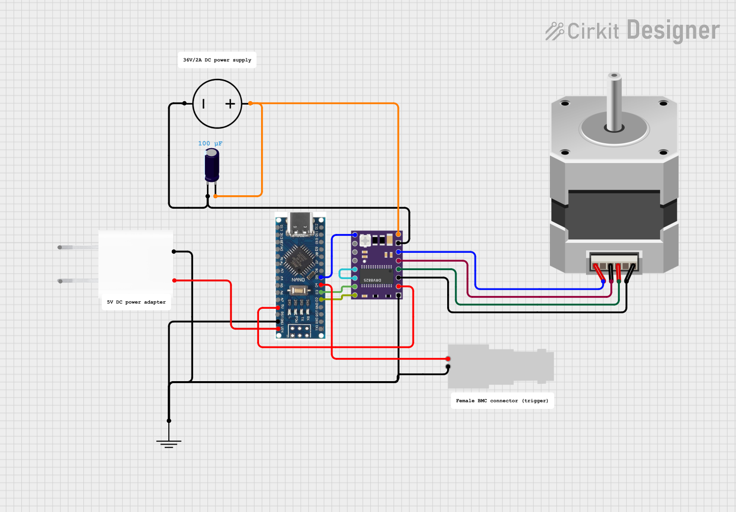
Example: Connecting to an Arduino UNO
Below is an example of how to control a DC motor using the DRV8833 and an Arduino UNO.
Circuit Connections
- DRV8833 Pin ENABLEA → Arduino Pin 9 (PWM output)
- DRV8833 Pin PHASEA → Arduino Pin 8 (digital output)
- DRV8833 Pin VM → External power supply (e.g., 6V for the motor)
- DRV8833 Pin VCC → Arduino 5V
- DRV8833 Pin GND → Arduino GND and motor power supply GND
- DRV8833 Pins AOUT1, AOUT2 → Motor terminals
Arduino Code
// DRV8833 Motor Driver Example
// Controls the speed and direction of a DC motor using Arduino

#define ENABLEA 9  // PWM pin for motor speed control
#define PHASEA 8   // Digital pin for motor direction control

void setup() {
  pinMode(ENABLEA, OUTPUT); // Set ENABLEA as output
  pinMode(PHASEA, OUTPUT);  // Set PHASEA as output
}

void loop() {
  // Rotate motor forward at 50% speed
  digitalWrite(PHASEA, HIGH); // Set direction forward
  analogWrite(ENABLEA, 128);  // Set speed (128/255 = 50%)
  delay(2000);                // Run for 2 seconds

  // Rotate motor backward at 75% speed
  digitalWrite(PHASEA, LOW);  // Set direction backward
  analogWrite(ENABLEA, 192);  // Set speed (192/255 = 75%)
  delay(2000);                // Run for 2 seconds

  // Stop the motor
  analogWrite(ENABLEA, 0);    // Set speed to 0
  delay(2000);                // Wait for 2 seconds
}
Important Considerations and Best Practices
- Ensure the motor's current and voltage ratings are within the DRV8833's limits.
- Use appropriate heat dissipation methods if operating near the maximum current rating.
- Avoid shorting the output pins, as this may trigger overcurrent protection or damage the device.
- Use a common ground for the motor power supply, logic power supply, and control signals.
Troubleshooting and FAQs
Common Issues and Solutions
Motor Not Spinning:
- Check the power supply connections (VM and VCC).
- Verify that the ENABLE pins are set high.
- Ensure the motor is properly connected to the output pins.
Motor Spins in the Wrong Direction:
- Reverse the logic level on the PHASE pin for the corresponding H-bridge.
Motor Speed is Inconsistent:
- Check the PWM signal for noise or instability.
- Ensure the power supply voltage is stable and within the specified range.
Overheating:
- Reduce the motor load or current draw.
- Add a heatsink or improve ventilation around the DRV8833.
No Output from the Driver:
- Verify that the logic voltage (VCC) is within the specified range.
- Check for any short circuits or incorrect wiring.
FAQs
Q: Can the DRV8833 drive stepper motors?
A: Yes, the DRV8833 can drive stepper motors by controlling both H-bridges. You will need to generate the appropriate step and direction signals.
Q: What is the maximum PWM frequency supported?
A: The DRV8833 supports PWM frequencies up to 250 kHz.
Q: Can I use the DRV8833 with a 3.3V microcontroller?
A: Yes, the DRV8833 is compatible with logic levels as low as 1.8V, making it suitable for 3.3V microcontrollers.
Q: Does the DRV8833 have built-in protection features?
A: Yes, it includes thermal shutdown, overcurrent protection, and undervoltage lockout for safe operation.