How to Use IR Transmitter: Examples, Pinouts, and Specs
Introduction
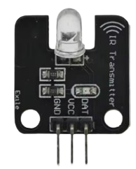
An IR Transmitter is an electronic component that emits infrared light signals, typically in the wavelength range of 850 nm to 950 nm. It is widely used in remote control applications, enabling wireless communication between devices by transmitting encoded data. The IR Transmitter is a key component in consumer electronics, such as TVs, air conditioners, and other appliances, as well as in robotics and IoT systems.
Explore Projects Built with IR Transmitter
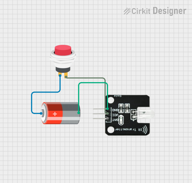
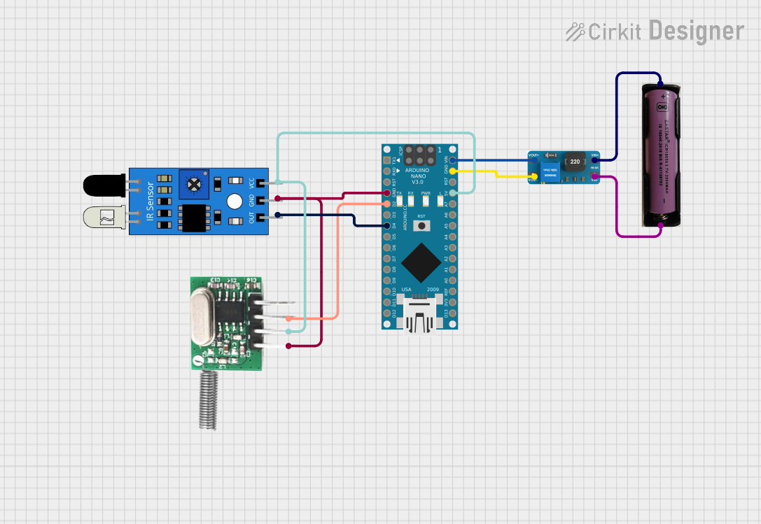

Explore Projects Built with IR Transmitter
Common Applications and Use Cases
- Remote controls for TVs, air conditioners, and other appliances
- Wireless communication in robotics and IoT devices
- Data transmission in short-range communication systems
- Proximity sensors and object detection systems
Technical Specifications
Below are the key technical details for the IR Transmitter manufactured by fart (Part ID: fart):
| Parameter | Value |
|---|---|
| Wavelength | 850 nm to 950 nm |
| Forward Voltage (Vf) | 1.2V to 1.5V |
| Forward Current (If) | 20 mA (typical), 50 mA (max) |
| Power Dissipation | 100 mW (max) |
| Beam Angle | 20° to 30° |
| Operating Temperature | -25°C to +85°C |
| Storage Temperature | -40°C to +100°C |
Pin Configuration and Descriptions
The IR Transmitter typically has two pins:
| Pin | Name | Description |
|---|---|---|
| 1 | Anode (+) | Connect to the positive terminal of the power supply |
| 2 | Cathode (-) | Connect to the ground or negative terminal |
Usage Instructions
How to Use the IR Transmitter in a Circuit
- Power Supply: Connect the anode (+) pin to a current-limiting resistor and then to the positive terminal of the power supply. The cathode (-) pin should be connected to the ground.
- Current Limiting: Use a resistor to limit the current through the IR Transmitter. For a 5V power supply, a 220Ω resistor is commonly used to ensure the current does not exceed 20 mA.
- Signal Modulation: To transmit data, the IR Transmitter must be driven with a modulated signal, typically at 38 kHz. This can be achieved using a microcontroller like an Arduino.
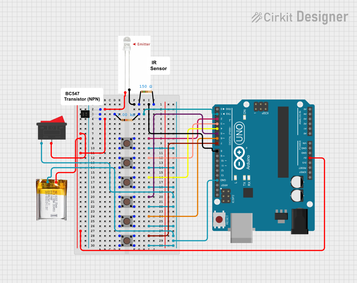
Example Circuit with Arduino UNO
Below is an example of how to connect and use the IR Transmitter with an Arduino UNO to send a 38 kHz modulated signal:
Circuit Diagram
- Connect the anode (+) of the IR Transmitter to a 220Ω resistor, and then to Arduino pin 3.
- Connect the cathode (-) of the IR Transmitter to the ground (GND) pin of the Arduino.
Arduino Code
// This code sends a 38 kHz modulated signal using an IR Transmitter
// connected to pin 3 of the Arduino UNO.

int irPin = 3; // IR Transmitter connected to digital pin 3

void setup() {
  pinMode(irPin, OUTPUT); // Set the IR pin as an output
}

void loop() {
  // Send a 38 kHz signal for 1 second
  for (int i = 0; i < 1000; i++) {
    digitalWrite(irPin, HIGH); // Turn the IR LED on
    delayMicroseconds(13);     // 13 microseconds for 38 kHz HIGH pulse
    digitalWrite(irPin, LOW);  // Turn the IR LED off
    delayMicroseconds(13);     // 13 microseconds for 38 kHz LOW pulse
  }
  delay(1000); // Wait for 1 second before repeating
}
Important Considerations and Best Practices
- Current Limiting: Always use a resistor to limit the current through the IR Transmitter to prevent damage.
- Modulation Frequency: Ensure the modulation frequency matches the receiver's requirements (typically 38 kHz).
- Line of Sight: IR signals require a clear line of sight between the transmitter and receiver for optimal performance.
- Ambient Light: Avoid using the IR Transmitter in environments with strong ambient light, as it may interfere with the signal.
Troubleshooting and FAQs
Common Issues and Solutions
IR Transmitter Not Working
- Cause: Incorrect wiring or missing current-limiting resistor.
- Solution: Double-check the connections and ensure a resistor is used to limit the current.
Weak Signal or Short Range
- Cause: Insufficient current or incorrect modulation frequency.
- Solution: Verify the resistor value and ensure the modulation frequency matches the receiver's requirements.
Interference from Ambient Light
- Cause: Strong sunlight or fluorescent lighting interfering with the IR signal.
- Solution: Use the IR Transmitter in a controlled environment or shield it from ambient light.
Receiver Not Responding
- Cause: Misalignment or incorrect modulation frequency.
- Solution: Align the transmitter and receiver properly and confirm the modulation frequency.
FAQs
Q: Can I use the IR Transmitter without modulation?
A: No, most IR receivers require a modulated signal (e.g., 38 kHz) to differentiate the IR signal from ambient light.
Q: What is the maximum range of the IR Transmitter?
A: The range depends on the power of the IR Transmitter and the sensitivity of the receiver. Typically, it ranges from 5 to 10 meters in indoor environments.
Q: Can I use the IR Transmitter with a 3.3V microcontroller?
A: Yes, but ensure the forward voltage and current requirements are met. Adjust the resistor value accordingly to limit the current.
Q: How do I test if the IR Transmitter is working?
A: Use a smartphone camera to view the IR Transmitter while it is active. The camera can detect infrared light, which will appear as a faint purple glow.