Cirkit Designer Logo
Cirkit Designer
Your all-in-one circuit design IDE
Home / 
Component Documentation

How to Use MCP23017: Examples, Pinouts, and Specs

Image of MCP23017
Cirkit Designer LogoDesign with MCP23017 in Cirkit Designer

Introduction

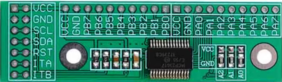
The MCP23017 is a 16-bit I/O expander that communicates via the I2C protocol. It allows microcontrollers to expand their GPIO capabilities by providing 16 additional general-purpose input/output (GPIO) pins. This makes it an ideal solution for applications requiring a large number of I/O pins without increasing the microcontroller's pin count.

Explore Projects Built with MCP23017

Use Cirkit Designer to design, explore, and prototype these projects online. Some projects support real-time simulation. Click "Open Project" to start designing instantly!
MCP23017-Expanded I/O Interface with ADS1115 ADC and ESP32 Control
Image of door and window sensors: A project utilizing MCP23017 in a practical application
This circuit features two MCP23017 I/O expanders interfaced with multiple switches, allowing for the expansion of input capabilities. The MCP23017s are connected via I2C to an Olimex ESP32-EVB microcontroller, which likely manages the input states from the switches. Additionally, an Adafruit ADS1115 16-bit ADC is included, suggesting that some analog inputs are being monitored, with the ADC also interfaced with the ESP32 via I2C.
Cirkit Designer LogoOpen Project in Cirkit Designer
I2C-Controlled Relay Switching with ESP32 and MCP23017 for Home Automation
Image of Vloerverwarming: A project utilizing MCP23017 in a practical application
This circuit appears to be a control system utilizing two MCP23017 I/O expanders interfaced with an Olimex ESP32-EVB microcontroller via I2C communication, as indicated by the SDA and SCL connections with pull-up resistors. The MCP23017 expanders control an 8-channel relay module, allowing the microcontroller to switch various loads, potentially for home automation or industrial control. Additionally, there is an Adafruit ADS1115 16-bit ADC for analog signal measurement, and several heating actuators and a thermostat are connected, suggesting temperature control functionality.
Cirkit Designer LogoOpen Project in Cirkit Designer
ESP32-Based I2C Communication Hub with Multiplexer and Expander
Image of Lights: A project utilizing MCP23017 in a practical application
This circuit features an Olimex ESP32-EVB microcontroller unit (MCU) for processing and connectivity, interfaced with an MCP23017 I/O expander and an Adafruit TCA9548A I2C multiplexer to expand the number of I/O lines and allow multiple I2C devices to communicate with the MCU over the same bus. Pull-up resistors are connected to the I2C lines for proper bus operation, and both the MCP23017 and TCA9548A have their reset lines pulled high, likely for normal operation without external reset control.
Cirkit Designer LogoOpen Project in Cirkit Designer
ESP32-Based Vibration Motor Controller with I2C IO Expansion
Image of VIBRATYION: A project utilizing MCP23017 in a practical application
This circuit features an ESP32 Wroom Dev Kit microcontroller interfaced with an MCP23017 I/O expansion board via I2C communication, utilizing GPIO 21 and GPIO 22 for SDA and SCL lines, respectively. A vibration motor is controlled by an NPN transistor acting as a switch, with a diode for back EMF protection and a resistor to limit base current. The ESP32 can control the motor by sending signals to the MCP23017, which then interfaces with the transistor to turn the motor on or off.
Cirkit Designer LogoOpen Project in Cirkit Designer

Explore Projects Built with MCP23017

Use Cirkit Designer to design, explore, and prototype these projects online. Some projects support real-time simulation. Click "Open Project" to start designing instantly!
Image of door and window sensors: A project utilizing MCP23017 in a practical application
MCP23017-Expanded I/O Interface with ADS1115 ADC and ESP32 Control
This circuit features two MCP23017 I/O expanders interfaced with multiple switches, allowing for the expansion of input capabilities. The MCP23017s are connected via I2C to an Olimex ESP32-EVB microcontroller, which likely manages the input states from the switches. Additionally, an Adafruit ADS1115 16-bit ADC is included, suggesting that some analog inputs are being monitored, with the ADC also interfaced with the ESP32 via I2C.
Cirkit Designer LogoOpen Project in Cirkit Designer
Image of Vloerverwarming: A project utilizing MCP23017 in a practical application
I2C-Controlled Relay Switching with ESP32 and MCP23017 for Home Automation
This circuit appears to be a control system utilizing two MCP23017 I/O expanders interfaced with an Olimex ESP32-EVB microcontroller via I2C communication, as indicated by the SDA and SCL connections with pull-up resistors. The MCP23017 expanders control an 8-channel relay module, allowing the microcontroller to switch various loads, potentially for home automation or industrial control. Additionally, there is an Adafruit ADS1115 16-bit ADC for analog signal measurement, and several heating actuators and a thermostat are connected, suggesting temperature control functionality.
Cirkit Designer LogoOpen Project in Cirkit Designer
Image of Lights: A project utilizing MCP23017 in a practical application
ESP32-Based I2C Communication Hub with Multiplexer and Expander
This circuit features an Olimex ESP32-EVB microcontroller unit (MCU) for processing and connectivity, interfaced with an MCP23017 I/O expander and an Adafruit TCA9548A I2C multiplexer to expand the number of I/O lines and allow multiple I2C devices to communicate with the MCU over the same bus. Pull-up resistors are connected to the I2C lines for proper bus operation, and both the MCP23017 and TCA9548A have their reset lines pulled high, likely for normal operation without external reset control.
Cirkit Designer LogoOpen Project in Cirkit Designer
Image of VIBRATYION: A project utilizing MCP23017 in a practical application
ESP32-Based Vibration Motor Controller with I2C IO Expansion
This circuit features an ESP32 Wroom Dev Kit microcontroller interfaced with an MCP23017 I/O expansion board via I2C communication, utilizing GPIO 21 and GPIO 22 for SDA and SCL lines, respectively. A vibration motor is controlled by an NPN transistor acting as a switch, with a diode for back EMF protection and a resistor to limit base current. The ESP32 can control the motor by sending signals to the MCP23017, which then interfaces with the transistor to turn the motor on or off.
Cirkit Designer LogoOpen Project in Cirkit Designer

Common Applications and Use Cases

  • Expanding GPIO pins for microcontrollers like Arduino, Raspberry Pi, or ESP32
  • Driving LEDs, relays, or other output devices
  • Reading multiple switches, buttons, or sensors
  • Home automation systems
  • Industrial control systems

Technical Specifications

  • Communication Protocol: I2C (Inter-Integrated Circuit)
  • Operating Voltage: 1.8V to 5.5V
  • Maximum I2C Clock Frequency: 1.7 MHz
  • Number of GPIO Pins: 16 (organized into two 8-bit ports: PORTA and PORTB)
  • GPIO Modes: Input, Output, Input with Pull-up
  • Interrupt Capability: Configurable interrupt-on-change for each pin
  • Package Types: PDIP, SOIC, SSOP, QFN
  • Operating Temperature Range: -40°C to +125°C

Pin Configuration and Descriptions

The MCP23017 has 28 pins. Below is the pin configuration:

Pin Name Description
1-3 A0, A1, A2 I2C address selection pins (used to set the I2C address of the device)
4 RESET Active-low reset input
5 INTB Interrupt output for PORTB
6 INTA Interrupt output for PORTA
7 VSS Ground (0V)
8-15 GPA0-GPA7 GPIO pins for PORTA
16 VDD Power supply (1.8V to 5.5V)
17-24 GPB0-GPB7 GPIO pins for PORTB
25 SCL I2C clock input
26 SDA I2C data input/output
27 NC No connection
28 NC No connection

Usage Instructions

How to Use the MCP23017 in a Circuit

  1. Powering the MCP23017: Connect the VDD pin to a power source (1.8V to 5.5V) and the VSS pin to ground.
  2. I2C Address Configuration: Use the A0, A1, and A2 pins to set the I2C address. Each pin can be connected to VDD (logic high) or VSS (logic low), allowing up to 8 unique addresses.
  3. Connecting to a Microcontroller:
    • Connect the SCL pin to the microcontroller's I2C clock line.
    • Connect the SDA pin to the microcontroller's I2C data line.
    • Use pull-up resistors (typically 4.7kΩ) on the SCL and SDA lines.
  4. GPIO Configuration:
    • Configure each GPIO pin as input or output by writing to the IODIRA and IODIRB registers.
    • Enable internal pull-up resistors for input pins by writing to the GPPUA and GPPUB registers.
    • Read or write to GPIO pins using the GPIOA and GPIOB registers.

Important Considerations and Best Practices

  • Interrupts: Use the INTA and INTB pins to handle interrupt-on-change events for PORTA and PORTB, respectively. Configure interrupt behavior using the INTCONA, INTCONB, and GPINTENA/GPINTENB registers.
  • I2C Pull-up Resistors: Ensure proper pull-up resistors are used on the I2C lines to maintain signal integrity.
  • Voltage Levels: Ensure the voltage levels of the MCP23017 and the microcontroller are compatible. Use level shifters if necessary.
  • Unused Pins: Leave unused GPIO pins unconnected or configure them as outputs to avoid floating inputs.

Example: Using MCP23017 with Arduino UNO

Below is an example of how to use the MCP23017 with an Arduino UNO to control LEDs connected to PORTA.

Circuit Diagram

  • Connect MCP23017's VDD to 5V and VSS to GND.
  • Connect SCL and SDA to Arduino's A5 and A4 pins, respectively.
  • Connect LEDs to GPA0-GPA7 with current-limiting resistors.

Arduino Code

#include <Wire.h> // Include the Wire library for I2C communication

#define MCP23017_ADDRESS 0x20 // Default I2C address of MCP23017

void setup() {
  Wire.begin(); // Initialize I2C communication
  // Set all PORTA pins as outputs
  Wire.beginTransmission(MCP23017_ADDRESS);
  Wire.write(0x00); // IODIRA register address
  Wire.write(0x00); // Set all pins on PORTA as outputs
  Wire.endTransmission();
}

void loop() {
  // Turn on all LEDs connected to PORTA
  Wire.beginTransmission(MCP23017_ADDRESS);
  Wire.write(0x12); // GPIOA register address
  Wire.write(0xFF); // Set all PORTA pins high
  Wire.endTransmission();
  delay(1000); // Wait for 1 second

  // Turn off all LEDs connected to PORTA
  Wire.beginTransmission(MCP23017_ADDRESS);
  Wire.write(0x12); // GPIOA register address
  Wire.write(0x00); // Set all PORTA pins low
  Wire.endTransmission();
  delay(1000); // Wait for 1 second
}

Troubleshooting and FAQs

Common Issues

  1. MCP23017 Not Responding on I2C Bus:

    • Cause: Incorrect I2C address or wiring.
    • Solution: Verify the A0, A1, and A2 pin configuration and ensure proper connections to SDA and SCL.
  2. GPIO Pins Not Functioning as Expected:

    • Cause: Incorrect configuration of IODIR, GPPU, or GPIO registers.
    • Solution: Double-check the register settings for input/output modes and pull-up resistors.
  3. Interrupts Not Triggering:

    • Cause: Interrupts not enabled or misconfigured.
    • Solution: Ensure GPINTEN, INTCON, and DEFVAL registers are configured correctly.
  4. I2C Communication Errors:

    • Cause: Missing or incorrect pull-up resistors on SDA/SCL lines.
    • Solution: Add 4.7kΩ pull-up resistors to the SDA and SCL lines.

FAQs

  • Q: Can I use multiple MCP23017 devices on the same I2C bus?

    • A: Yes, up to 8 devices can be used by configuring unique I2C addresses using the A0, A1, and A2 pins.
  • Q: What is the maximum current each GPIO pin can source or sink?

    • A: Each GPIO pin can source or sink up to 25mA, with a total maximum current of 125mA for all pins combined.
  • Q: Can the MCP23017 operate at 3.3V?

    • A: Yes, the MCP23017 supports operating voltages from 1.8V to 5.5V, making it compatible with 3.3V systems.
  • Q: Do I need external pull-up resistors for input pins?

    • A: No, the MCP23017 has internal pull-up resistors that can be enabled via the GPPU registers.