
How to Use CMA3000-D01: Examples, Pinouts, and Specs
 Design with CMA3000-D01 in Cirkit Designer
Introduction
The CMA3000-D01 is a high-performance analog-to-digital converter (ADC) designed for precision measurement applications. It offers a high sampling rate and low noise, making it ideal for converting analog signals into digital data with exceptional accuracy. This component is widely used in industrial and consumer electronics for signal processing tasks, including data acquisition systems, audio processing, and sensor interfacing.
Explore Projects Built with CMA3000-D01
 Open Project in Cirkit Designer
 Open Project in Cirkit Designer
 Open Project in Cirkit Designer
 Open Project in Cirkit Designer
Explore Projects Built with CMA3000-D01
Open Project in Cirkit DesignerOpen Project in Cirkit DesignerOpen Project in Cirkit DesignerOpen Project in Cirkit DesignerCommon Applications
- Data acquisition systems in industrial automation
- Audio signal processing
- Precision measurement in scientific instruments
- Sensor interfacing in IoT devices
- Consumer electronics requiring high-resolution ADCs
Technical Specifications
The CMA3000-D01 is engineered to deliver reliable performance in demanding applications. Below are its key technical specifications:
| Parameter | Value |
|---|---|
| Supply Voltage | 2.7V to 3.6V |
| Input Voltage Range | 0V to VDD |
| Resolution | 16-bit |
| Sampling Rate | Up to 1 MSPS (Mega Samples Per Second) |
| Signal-to-Noise Ratio (SNR) | 92 dB |
| Power Consumption | 2.5 mW (typical) |
| Operating Temperature Range | -40°C to +85°C |
| Communication Interface | SPI |
Pin Configuration and Descriptions
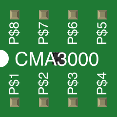
The CMA3000-D01 comes in a compact 8-pin package. Below is the pin configuration:
| Pin Number | Pin Name | Description |
|---|---|---|
| 1 | VDD | Positive supply voltage (2.7V to 3.6V) |
| 2 | GND | Ground |
| 3 | CS | Chip Select (active low) for SPI communication |
| 4 | SCLK | Serial Clock input for SPI |
| 5 | MOSI | Master Out Slave In (data input) |
| 6 | MISO | Master In Slave Out (data output) |
| 7 | IN+ | Positive analog input |
| 8 | IN- | Negative analog input |
Usage Instructions
How to Use the CMA3000-D01 in a Circuit
- Power Supply: Connect the VDD pin to a stable 3.3V power source and the GND pin to ground.
- Analog Input: Feed the differential analog signal to the IN+ and IN- pins. Ensure the input voltage stays within the specified range (0V to VDD).
- SPI Communication: Connect the SPI pins (CS, SCLK, MOSI, MISO) to a microcontroller or processor capable of SPI communication.
- Bypass Capacitor: Place a 0.1 µF ceramic capacitor close to the VDD pin to filter out noise.
- Sampling Rate: Configure the sampling rate via the SPI interface to match your application requirements.
Important Considerations
- Input Impedance: Ensure the source impedance of the analog signal is low to avoid signal degradation.
- Noise Reduction: Use proper grounding and shielding techniques to minimize noise in high-precision applications.
- SPI Configuration: Set the SPI clock polarity (CPOL) and phase (CPHA) according to the CMA3000-D01's requirements (CPOL = 0, CPHA = 0).
Example Code for Arduino UNO
Below is an example of how to interface the CMA3000-D01 with an Arduino UNO using SPI:
#include <SPI.h>

// Define SPI pins for the CMA3000-D01
const int CS_PIN = 10; // Chip Select pin

void setup() {
  // Initialize Serial Monitor for debugging
  Serial.begin(9600);

  // Configure SPI settings
  SPI.begin();
  SPI.setClockDivider(SPI_CLOCK_DIV16); // Set SPI clock speed
  SPI.setDataMode(SPI_MODE0);           // CPOL = 0, CPHA = 0
  SPI.setBitOrder(MSBFIRST);            // Most Significant Bit first

  // Configure Chip Select pin
  pinMode(CS_PIN, OUTPUT);
  digitalWrite(CS_PIN, HIGH); // Set CS high (inactive)
}

void loop() {
  // Example: Read data from the CMA3000-D01
  digitalWrite(CS_PIN, LOW); // Activate the chip by pulling CS low

  // Send a command to read data (example command: 0x10)
  byte command = 0x10;
  SPI.transfer(command);

  // Read the 16-bit ADC result
  byte highByte = SPI.transfer(0x00); // Read high byte
  byte lowByte = SPI.transfer(0x00);  // Read low byte
  digitalWrite(CS_PIN, HIGH);         // Deactivate the chip

  // Combine high and low bytes into a 16-bit value
  int adcValue = (highByte << 8) | lowByte;

  // Print the ADC value to the Serial Monitor
  Serial.print("ADC Value: ");
  Serial.println(adcValue);

  delay(1000); // Wait for 1 second before the next reading
}
Troubleshooting and FAQs
Common Issues
No Data Output:
- Cause: Incorrect SPI configuration or wiring.
- Solution: Verify SPI settings (clock speed, mode, and bit order) and ensure proper connections.
High Noise in ADC Output:
- Cause: Poor grounding or noisy power supply.
- Solution: Use a low-noise power supply and proper grounding techniques. Add decoupling capacitors near the component.
Incorrect ADC Values:
- Cause: Input signal exceeds the specified voltage range.
- Solution: Ensure the input signal stays within 0V to VDD.
FAQs
Q1: Can the CMA3000-D01 operate at 5V?
A1: No, the CMA3000-D01 operates within a supply voltage range of 2.7V to 3.6V. Exceeding this range may damage the component.
Q2: What is the maximum sampling rate of the CMA3000-D01?
A2: The maximum sampling rate is 1 MSPS (Mega Samples Per Second).
Q3: Does the CMA3000-D01 support single-ended input?
A3: No, the CMA3000-D01 is designed for differential input signals. For single-ended signals, use a differential amplifier to convert the signal.
Q4: How do I calculate the resolution of the ADC?
A4: The resolution is determined by the number of bits (16-bit). The smallest detectable change is VDD / 216. For a 3.3V supply, the resolution is approximately 50 µV.
By following this documentation, users can effectively integrate the CMA3000-D01 into their projects and troubleshoot common issues.