The RJ45 Macho connector is a male Ethernet connector widely used in networking applications. It is designed to terminate Ethernet cables, enabling the connection of devices such as computers, routers, switches, and other network equipment to a local area network (LAN) or the internet. The RJ45 Macho connector is a critical component in structured cabling systems, supporting high-speed data transmission and reliable communication.
Explore Projects Built with RJ45 Macho
Use Cirkit Designer to design, explore, and prototype these projects online. Some projects support real-time simulation. Click "Open Project" to start designing instantly!
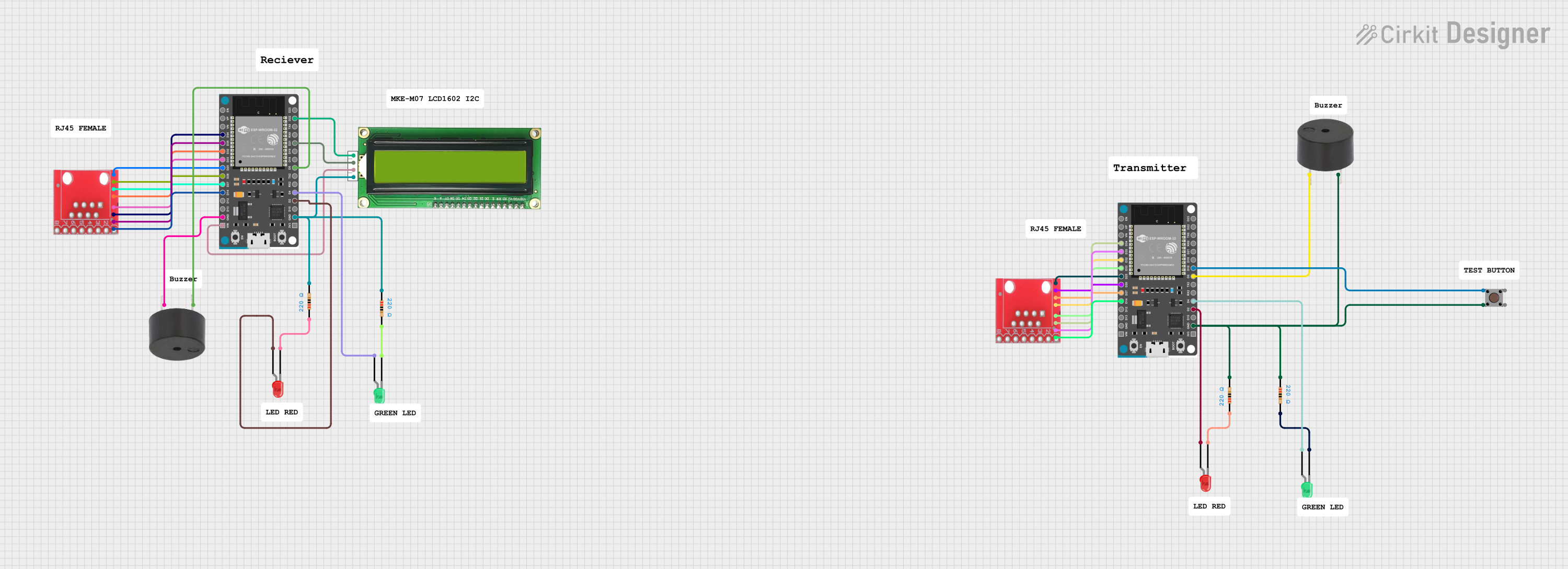
This circuit is a cable tester using two ESP32 microcontrollers to check the continuity and measure the length of RJ45 cables. It includes LEDs, a buzzer, and an LCD for visual and auditory feedback, and a pushbutton to initiate the test. The microcontrollers control the LEDs, buzzer, and LCD, and read the state of the RJ45 pins to determine connectivity and cable length.
This circuit describes a networked system where an Optiplex Micro computer is powered by a PC Power Supply and connected to a PC Screen via HDMI for display output. The computer is networked through an Ethernet Switch, which also connects to two PoE Cameras and a Toyopuc PLC. The Ethernet Switch is powered by a PoE PSU 48V DC, and all AC-powered devices are connected to a common 220V AC source.
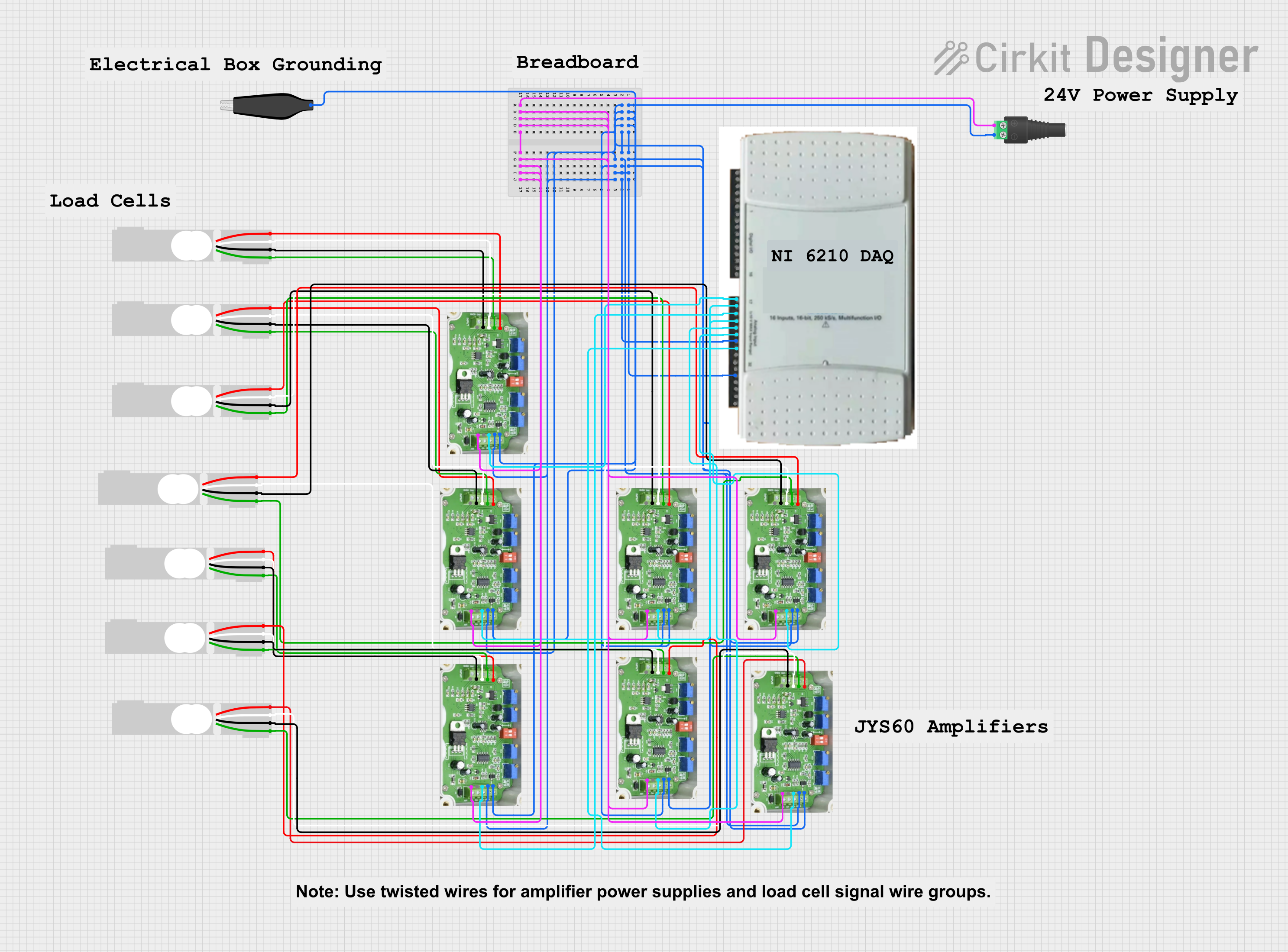
This is a multi-channel load cell measurement system with several JYS60 amplifiers connected to load cells for weight or force sensing. The amplified signals are directed to a DAQ system for data capture, and power is supplied through a barrel jack. Grounding is achieved via an AdaGator Side Black component.
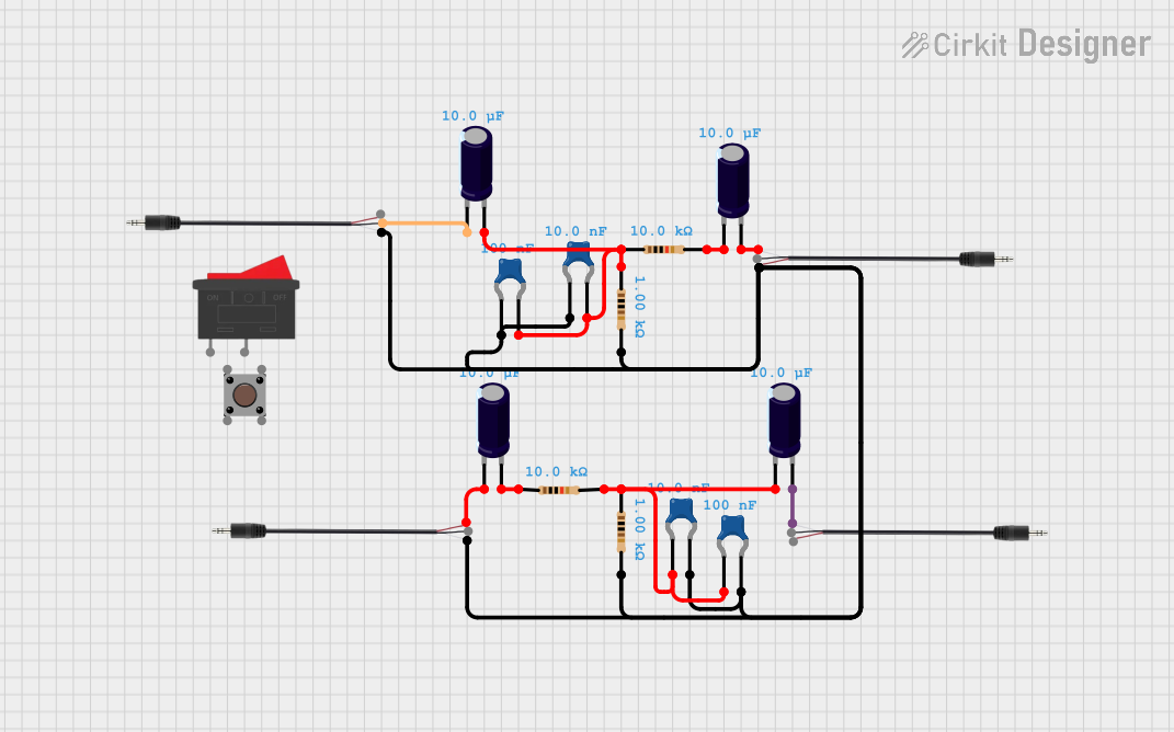
This circuit appears to be an audio signal processing or filtering circuit, utilizing multiple 3.5mm jacks for input and output connections, resistors, and capacitors to form various RC (resistor-capacitor) networks. The configuration suggests it could be used for tasks such as audio signal conditioning, noise filtering, or impedance matching.
Connecting computers, printers, and other devices to a LAN.
Establishing wired internet connections for routers and modems.
Terminating Ethernet cables in structured cabling installations.
Used in Power over Ethernet (PoE) applications to deliver power and data over a single cable.
Technical Specifications
The RJ45 Macho connector is standardized under the TIA/EIA-568 standard and is compatible with Ethernet cables such as Cat5, Cat5e, Cat6, and Cat6a. Below are the key technical details:
Key Technical Details
Connector Type: 8P8C (8 positions, 8 contacts)
Supported Cable Types: Cat5, Cat5e, Cat6, Cat6a
Maximum Data Rate: Up to 10 Gbps (depending on cable type)
Contact Material: Gold-plated contacts for corrosion resistance and improved conductivity
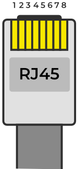
The RJ45 Macho connector has 8 pins, each corresponding to a specific wire in the Ethernet cable. The pinout follows either the T568A or T568B wiring standard. Below is the pin configuration:
T568A Wiring Standard
Pin Number
Wire Color
Signal Description
1
White/Green
Transmit Data + (TX+)
2
Green
Transmit Data - (TX-)
3
White/Orange
Receive Data + (RX+)
4
Blue
Unused (or PoE Power +)
5
White/Blue
Unused (or PoE Power +)
6
Orange
Receive Data - (RX-)
7
White/Brown
Unused (or PoE Power -)
8
Brown
Unused (or PoE Power -)
T568B Wiring Standard
Pin Number
Wire Color
Signal Description
1
White/Orange
Transmit Data + (TX+)
2
Orange
Transmit Data - (TX-)
3
White/Green
Receive Data + (RX+)
4
Blue
Unused (or PoE Power +)
5
White/Blue
Unused (or PoE Power +)
6
Green
Receive Data - (RX-)
7
White/Brown
Unused (or PoE Power -)
8
Brown
Unused (or PoE Power -)
Usage Instructions
How to Use the RJ45 Macho Connector in a Circuit
Prepare the Ethernet Cable:
Strip approximately 1 inch of the outer jacket from the Ethernet cable.
Untwist the wire pairs and arrange them according to the T568A or T568B wiring standard.
Insert the Wires into the Connector:
Align the wires in the correct order and trim them to ensure they are of equal length.
Insert the wires into the RJ45 Macho connector, ensuring each wire reaches the end of its respective slot.
Crimp the Connector:
Use an RJ45 crimping tool to secure the connector to the cable.
Apply firm pressure to ensure the contacts pierce the wire insulation and establish a connection.
Test the Connection:
Use a cable tester to verify the continuity and correct wiring of the terminated cable.
Important Considerations and Best Practices
Always use high-quality RJ45 connectors and cables to ensure reliable performance.
Follow the T568A or T568B wiring standard consistently throughout the installation.
Avoid excessive bending or pulling of the Ethernet cable to prevent damage.
For PoE applications, ensure the connector and cable are rated for the required power level.
Example: Connecting to an Arduino UNO
While the RJ45 Macho connector itself is not directly connected to an Arduino UNO, it can be used with an Ethernet shield to enable network communication. Below is an example of Arduino code for using an Ethernet shield with an RJ45 Macho connector:
#include <SPI.h>
#include <Ethernet.h>

// MAC address and IP address for the Ethernet shield
byte mac[] = { 0xDE, 0xAD, 0xBE, 0xEF, 0xFE, 0xED };
IPAddress ip(192, 168, 1, 177);

// Initialize the Ethernet server on port 80
EthernetServer server(80);

void setup() {
  // Start the Ethernet connection
  Ethernet.begin(mac, ip);

  // Start the server
  server.begin();
  Serial.begin(9600);
  Serial.println("Server is ready at IP: ");
  Serial.println(Ethernet.localIP());
}

void loop() {
  // Listen for incoming clients
  EthernetClient client = server.available();
  if (client) {
    Serial.println("New client connected");
    while (client.connected()) {
      if (client.available()) {
        char c = client.read();
        Serial.write(c); // Echo the received data to the Serial Monitor
      }
    }
    client.stop();
    Serial.println("Client disconnected");
  }
}
Troubleshooting and FAQs
Common Issues and Solutions
Issue: The Ethernet cable does not work after termination.
Solution: Verify the wiring order (T568A or T568B) and ensure the wires are fully inserted into the connector. Use a cable tester to check for continuity.
Issue: Poor network performance or intermittent connection.
Solution: Check for loose connections or damaged cables. Ensure the RJ45 Macho connector is properly crimped and the contacts are clean.
Issue: The connector does not fit into the Ethernet port.
Solution: Ensure the connector is an RJ45 type and not a similar-looking connector (e.g., RJ11). Check for physical obstructions or damage to the port.
FAQs
Q: Can I reuse an RJ45 Macho connector? A: No, RJ45 connectors are designed for one-time use. Reusing them may result in unreliable connections.
Q: What is the difference between T568A and T568B wiring standards? A: The difference lies in the arrangement of wire colors. Both standards are functionally equivalent, but T568B is more commonly used in the United States.
Q: Can the RJ45 Macho connector be used for PoE? A: Yes, the RJ45 Macho connector supports Power over Ethernet (PoE) when used with compatible cables and devices.

 Open Project in Cirkit Designer