How to Use Arduino UNO SMD: Examples, Pinouts, and Specs
Introduction
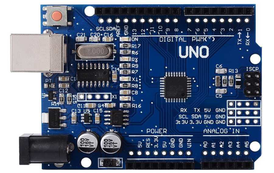
The Arduino UNO SMD is a compact version of the popular Arduino UNO microcontroller board, manufactured by Arduino S.r.l. It features surface-mount technology (SMD) for a smaller footprint, making it ideal for embedded projects and prototyping where space is a constraint. The board is based on the ATmega328P microcontroller and retains the same functionality as the standard Arduino UNO, with a few minor differences in design.
Explore Projects Built with Arduino UNO SMD
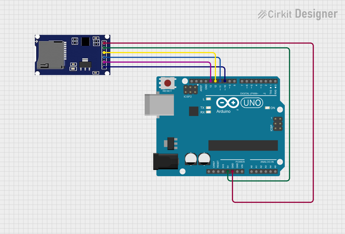
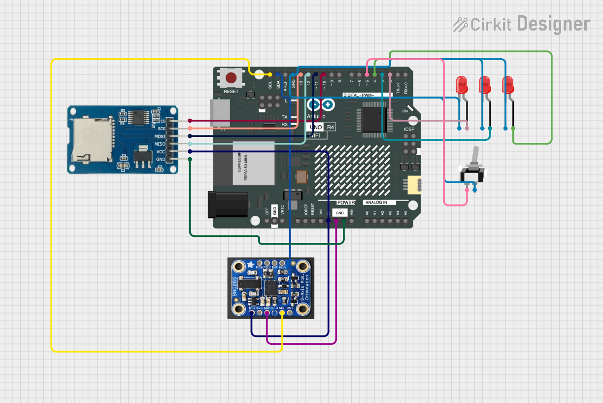
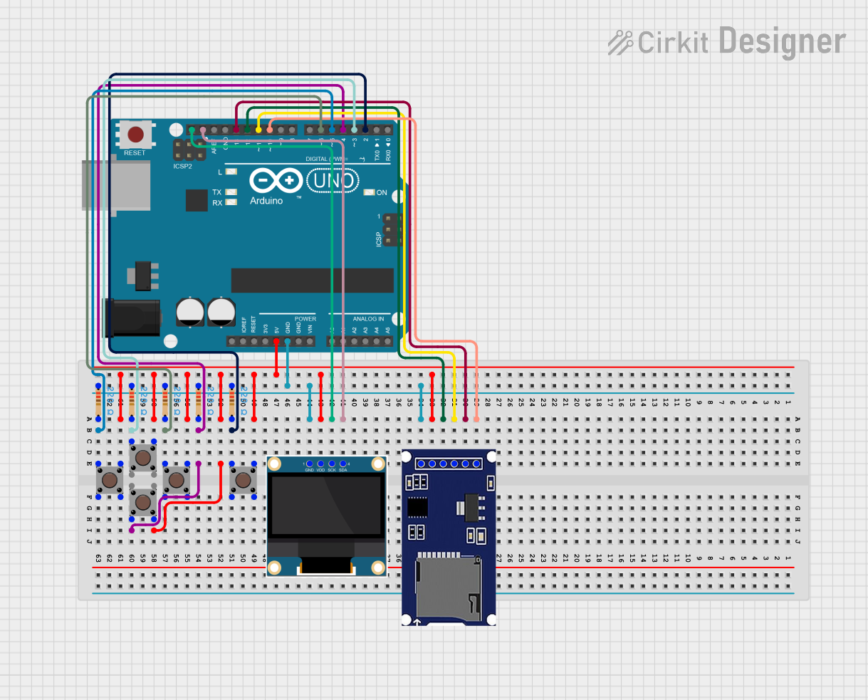
Explore Projects Built with Arduino UNO SMD
Common Applications and Use Cases
- Prototyping and development of embedded systems
- IoT (Internet of Things) projects
- Robotics and automation
- Educational purposes for learning microcontroller programming
- Compact designs requiring a smaller PCB footprint
Technical Specifications
The following table outlines the key technical details of the Arduino UNO SMD:
| Specification | Details |
|---|---|
| Microcontroller | ATmega328P (SMD version) |
| Operating Voltage | 5V |
| Input Voltage (recommended) | 7-12V |
| Input Voltage (limit) | 6-20V |
| Digital I/O Pins | 14 (6 of which provide PWM output) |
| Analog Input Pins | 6 |
| DC Current per I/O Pin | 20 mA |
| Flash Memory | 32 KB (0.5 KB used by bootloader) |
| SRAM | 2 KB |
| EEPROM | 1 KB |
| Clock Speed | 16 MHz |
| USB Connector | Type-B |
| Dimensions | 68.6 mm x 53.4 mm |
| Weight | Approximately 25 g |
Pin Configuration and Descriptions
The Arduino UNO SMD has a total of 28 pins, including digital, analog, power, and communication pins. Below is a detailed description of the pin configuration:
Digital Pins
| Pin Number | Function | Description |
|---|---|---|
| D0 (RX) | UART Receive | Used for serial communication (receives data). |
| D1 (TX) | UART Transmit | Used for serial communication (transmits data). |
| D2-D13 | Digital I/O | General-purpose digital input/output pins. |
| D3, D5, D6, D9, D10, D11 | PWM Output | Provide Pulse Width Modulation (PWM) output. |
Analog Pins
| Pin Number | Function | Description |
|---|---|---|
| A0-A5 | Analog Input | Used to read analog signals (0-5V). |
Power Pins
| Pin Name | Function | Description |
|---|---|---|
| VIN | Input Voltage | External power input (7-12V recommended). |
| 5V | Regulated 5V Output | Provides 5V output for powering external components. |
| 3.3V | Regulated 3.3V Output | Provides 3.3V output for low-voltage components. |
| GND | Ground | Common ground connection. |
| RESET | Reset | Resets the microcontroller. |
Usage Instructions
How to Use the Arduino UNO SMD in a Circuit
Powering the Board:
- Connect the board to your computer using a USB Type-B cable for programming and power.
- Alternatively, use an external power supply (7-12V) via the VIN pin or DC barrel jack.
Programming the Board:
- Install the Arduino IDE from the official Arduino website.
- Select "Arduino UNO" as the board type in the IDE.
- Write your code in the IDE and upload it to the board using the USB connection.
Connecting Components:
- Use the digital and analog pins to connect sensors, actuators, and other peripherals.
- Ensure that the current drawn by connected components does not exceed the pin's maximum rating (20 mA).
Using PWM Pins:
- The PWM pins (D3, D5, D6, D9, D10, D11) can be used to control devices like LEDs or motors by varying the duty cycle.
Important Considerations and Best Practices
- Avoid exceeding the input voltage limit (20V) to prevent damage to the board.
- Use appropriate resistors when connecting LEDs or other components to prevent overcurrent.
- Ensure proper grounding for all connected components to avoid noise or erratic behavior.
- Use the RESET pin to restart the board if it becomes unresponsive.
Example Code for Arduino UNO SMD
Below is an example code to blink an LED connected to pin D13:
// Blink an LED connected to pin D13
// The LED will turn on for 1 second and off for 1 second repeatedly.

void setup() {
  pinMode(13, OUTPUT); // Set pin 13 as an output pin
}

void loop() {
  digitalWrite(13, HIGH); // Turn the LED on
  delay(1000);            // Wait for 1 second
  digitalWrite(13, LOW);  // Turn the LED off
  delay(1000);            // Wait for 1 second
}
Troubleshooting and FAQs
Common Issues and Solutions
The board is not detected by the computer:
- Ensure the USB cable is properly connected and functional.
- Check if the correct COM port is selected in the Arduino IDE.
- Install or update the USB drivers for the Arduino UNO.
Code upload fails:
- Verify that the correct board type ("Arduino UNO") is selected in the IDE.
- Press the RESET button on the board before uploading the code.
- Ensure no other application is using the COM port.
Components not working as expected:
- Double-check the wiring and connections.
- Ensure the components are compatible with the board's voltage and current ratings.
- Use a multimeter to test for continuity and proper voltage levels.
The board overheats:
- Check for short circuits in the connected components.
- Ensure the input voltage does not exceed the recommended range (7-12V).
- Avoid drawing excessive current from the pins.
FAQs
Q: Can I use the Arduino UNO SMD for wireless communication?
A: Yes, you can connect wireless modules like the ESP8266 or Bluetooth modules to the board via the UART or digital pins.
Q: Is the Arduino UNO SMD compatible with standard Arduino shields?
A: Yes, the Arduino UNO SMD has the same pin layout as the standard Arduino UNO, making it compatible with most shields.
Q: How is the SMD version different from the standard Arduino UNO?
A: The SMD version uses a surface-mount ATmega328P microcontroller, which reduces the board's size and weight. However, it is functionally identical to the standard version.