
How to Use RTC : Examples, Pinouts, and Specs
 Design with RTC in Cirkit Designer
Introduction
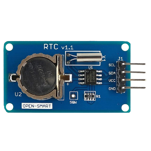
The DS1307 Real-Time Clock (RTC) module, manufactured by Baramee, is a timekeeping device designed to maintain accurate time and date information. It operates independently of the main system power, thanks to an onboard backup battery. The DS1307 is widely used in applications requiring precise timekeeping, such as data logging, alarms, and scheduling systems.
Explore Projects Built with RTC
 Open Project in Cirkit Designer
 Open Project in Cirkit Designer
 Open Project in Cirkit Designer
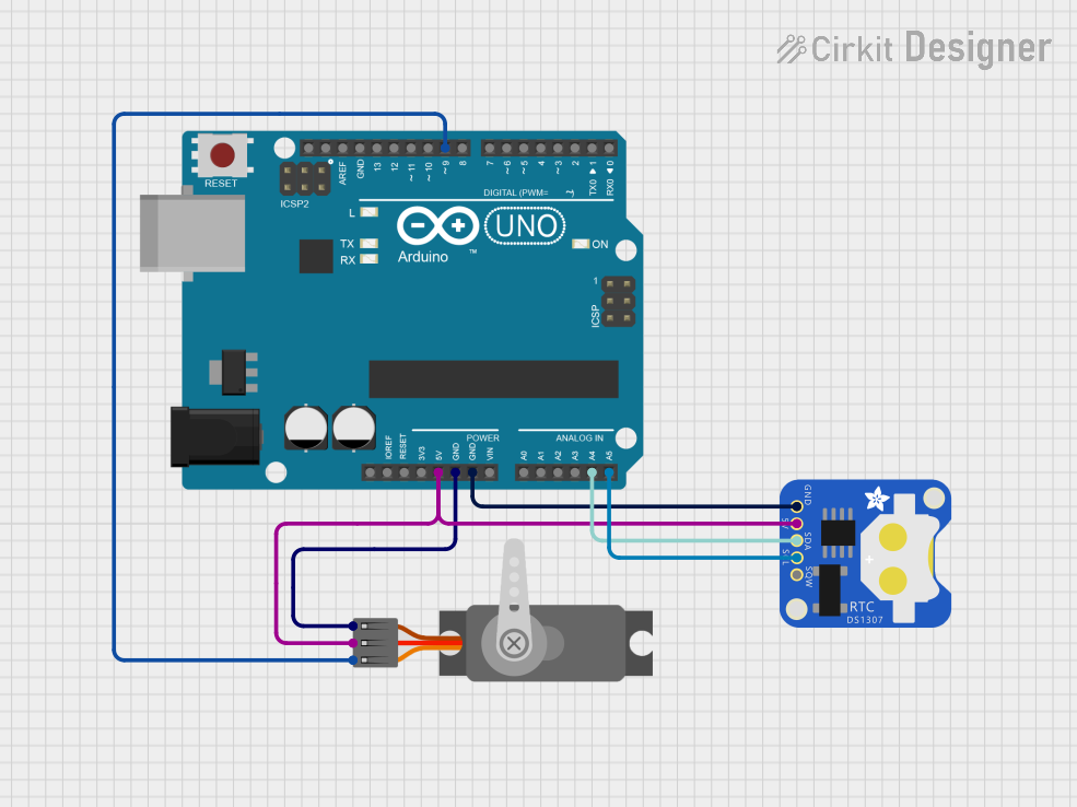 Open Project in Cirkit Designer
Explore Projects Built with RTC
Open Project in Cirkit DesignerOpen Project in Cirkit DesignerOpen Project in Cirkit DesignerOpen Project in Cirkit DesignerCommon Applications and Use Cases
- Time-stamping data in IoT devices
- Alarm clocks and timers
- Scheduling systems
- Home automation systems
- Embedded systems requiring persistent timekeeping
Technical Specifications
The DS1307 RTC module is a low-power, I2C-based timekeeping device. Below are its key technical details:
Key Technical Details
- Operating Voltage: 4.5V to 5.5V
- Backup Battery Voltage: 3.0V (typical CR2032 coin cell)
- Communication Protocol: I2C (Inter-Integrated Circuit)
- Clock Accuracy: ±2 seconds/day at 25°C
- Time Format: 12-hour or 24-hour with AM/PM indicator
- Date Format: Day, Month, Year (with Leap Year Compensation up to 2100)
- Operating Temperature Range: -40°C to +85°C
- Memory: 56 bytes of non-volatile RAM for user data storage
Pin Configuration and Descriptions
The DS1307 RTC module has 8 pins. The table below describes each pin:
| Pin Number | Pin Name | Description |
|---|---|---|
| 1 | X1 | External 32.768 kHz crystal oscillator input |
| 2 | X2 | External 32.768 kHz crystal oscillator output |
| 3 | VBAT | Backup battery input (connect to a 3V coin cell for power backup) |
| 4 | GND | Ground connection |
| 5 | SDA | Serial Data Line for I2C communication |
| 6 | SCL | Serial Clock Line for I2C communication |
| 7 | NC | Not connected (leave unconnected or use as a mechanical support point) |
| 8 | VCC | Main power supply input (4.5V to 5.5V) |
Usage Instructions
How to Use the DS1307 in a Circuit
- Power Supply: Connect the VCC pin to a 5V power source and the GND pin to ground. For backup power, connect a 3V coin cell battery to the VBAT pin.
- Crystal Oscillator: Attach a 32.768 kHz crystal oscillator to the X1 and X2 pins.
- I2C Communication: Connect the SDA and SCL pins to the corresponding I2C pins on your microcontroller (e.g., Arduino UNO).
- Pull-Up Resistors: Use 4.7kΩ pull-up resistors on the SDA and SCL lines for proper I2C operation.
- Programming: Use an appropriate library (e.g., RTClib for Arduino) to communicate with the DS1307 and set or retrieve time and date.
Important Considerations and Best Practices
- Ensure the backup battery is installed to maintain timekeeping during power outages.
- Avoid placing the crystal oscillator near high-frequency components to minimize interference.
- Use decoupling capacitors (e.g., 0.1µF) near the VCC pin to stabilize the power supply.
- Verify the I2C address of the DS1307 (default: 0x68) to avoid conflicts with other I2C devices.
Example Code for Arduino UNO
Below is an example of how to use the DS1307 RTC module with an Arduino UNO:
#include <Wire.h>
#include <RTClib.h>

// Create an RTC_DS1307 object
RTC_DS1307 rtc;

void setup() {
  Serial.begin(9600); // Initialize serial communication at 9600 baud
  Wire.begin();       // Initialize I2C communication

  if (!rtc.begin()) {
    Serial.println("Couldn't find RTC");
    while (1); // Halt the program if RTC is not found
  }

  if (!rtc.isrunning()) {
    Serial.println("RTC is NOT running, setting the time...");
    // Set the RTC to the current date and time
    rtc.adjust(DateTime(F(__DATE__), F(__TIME__)));
  }
}

void loop() {
  DateTime now = rtc.now(); // Get the current date and time

  // Print the current date and time to the Serial Monitor
  Serial.print(now.year(), DEC);
  Serial.print('/');
  Serial.print(now.month(), DEC);
  Serial.print('/');
  Serial.print(now.day(), DEC);
  Serial.print(" ");
  Serial.print(now.hour(), DEC);
  Serial.print(':');
  Serial.print(now.minute(), DEC);
  Serial.print(':');
  Serial.print(now.second(), DEC);
  Serial.println();

  delay(1000); // Wait for 1 second before updating
}
Troubleshooting and FAQs
Common Issues and Solutions
RTC Not Detected:
- Cause: Incorrect wiring or missing pull-up resistors on SDA/SCL lines.
- Solution: Double-check the wiring and ensure 4.7kΩ pull-up resistors are connected.
Time Resets After Power Loss:
- Cause: Backup battery is not connected or is depleted.
- Solution: Connect a 3V coin cell battery to the VBAT pin and verify its charge.
Incorrect Time or Date:
- Cause: RTC was not initialized or set correctly.
- Solution: Use the
rtc.adjust()function to set the correct time and date.
I2C Address Conflict:
- Cause: Another device on the I2C bus is using the same address (0x68).
- Solution: Check for address conflicts and reconfigure other devices if necessary.
FAQs
Q: Can the DS1307 operate without a backup battery?
A: Yes, but it will lose timekeeping functionality during power outages.Q: What is the maximum length of the I2C bus?
A: The I2C bus length should typically not exceed 1 meter to ensure reliable communication.Q: Can I use a different crystal oscillator frequency?
A: No, the DS1307 is designed to work specifically with a 32.768 kHz crystal oscillator.Q: How much data can I store in the DS1307's RAM?
A: The DS1307 provides 56 bytes of non-volatile RAM for user data storage.