How to Use FlySky Reciver FS-iA6B: Examples, Pinouts, and Specs
Introduction
The FlySky FS-iA6B is a 6-channel receiver designed for use in remote control (RC) systems. It provides reliable and stable communication between a FlySky transmitter and the controlled model, such as RC planes, cars, or drones. With its lightweight and compact design, the FS-iA6B is ideal for hobbyists and professionals seeking a dependable receiver for their RC projects. It supports i-BUS and PWM outputs, making it versatile for various applications.
Explore Projects Built with FlySky Reciver FS-iA6B
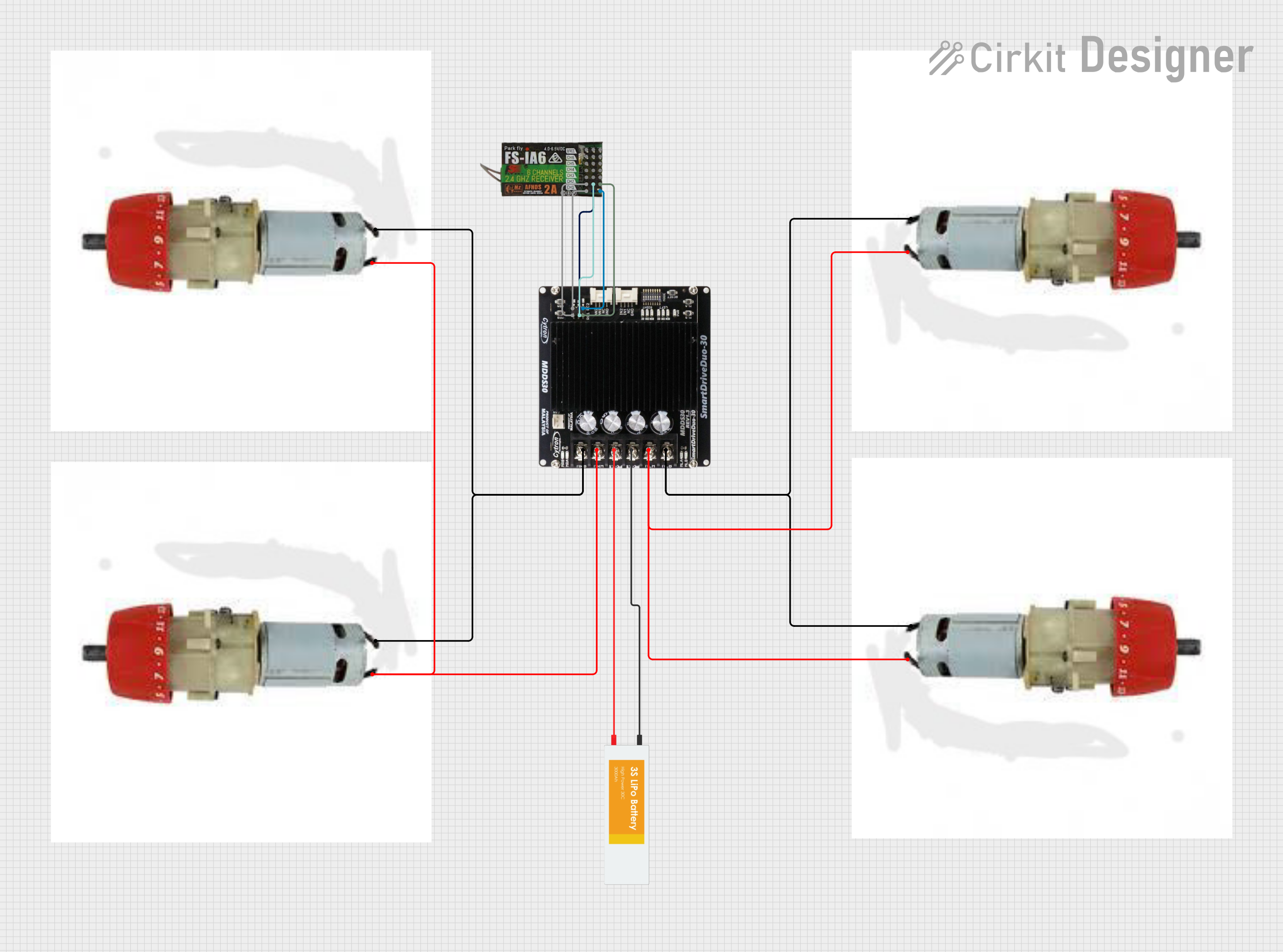
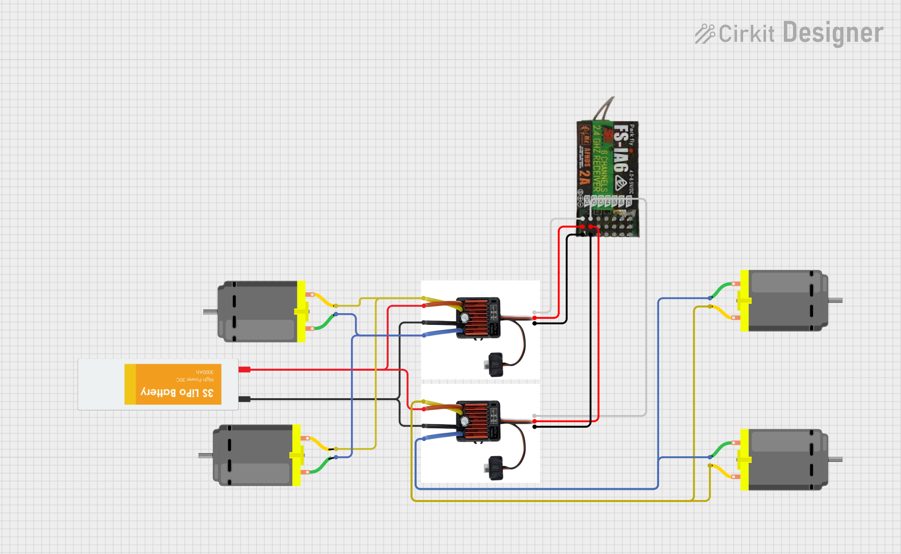
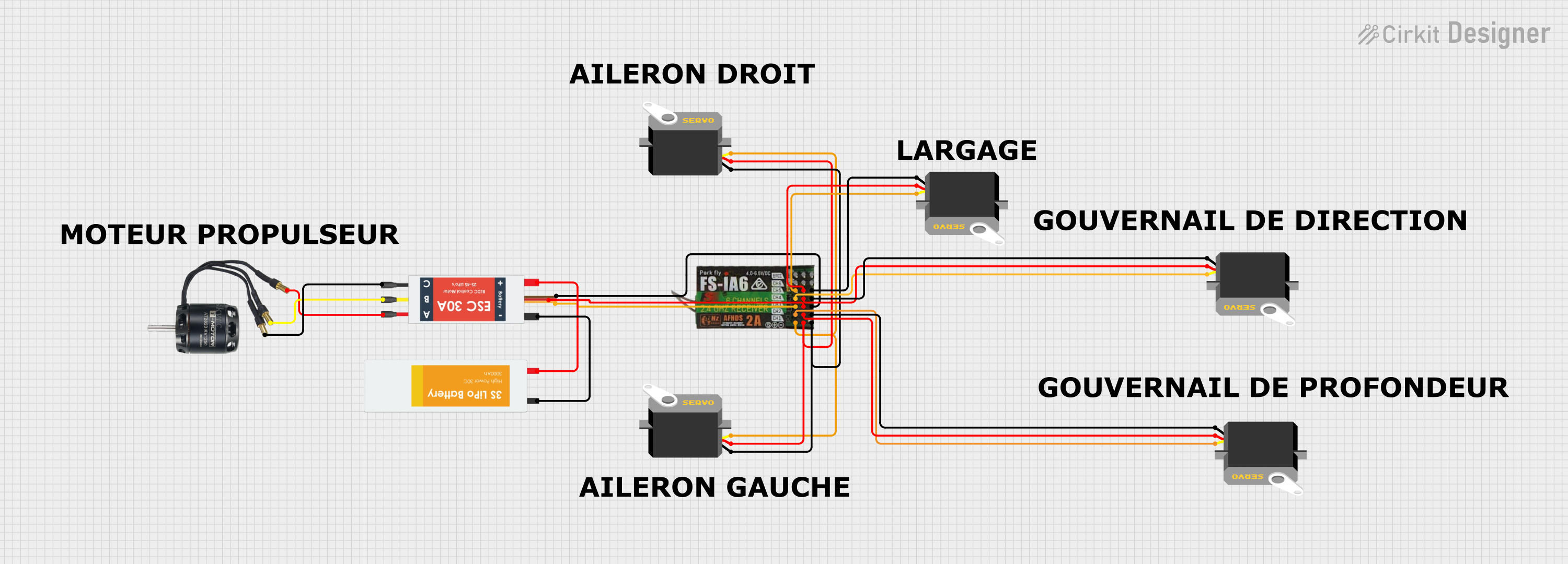
Explore Projects Built with FlySky Reciver FS-iA6B
Common Applications and Use Cases
- RC airplanes, helicopters, and drones
- RC cars and boats
- Robotics and automation projects
- Educational and hobbyist RC systems
- Projects requiring wireless communication between a transmitter and a model
Technical Specifications
The FS-iA6B receiver is designed to deliver high performance and reliability. Below are its key technical specifications:
| Specification | Details |
|---|---|
| Manufacturer | FlySky |
| Model Number | FS-iA6B |
| Channels | 6 |
| Frequency Range | 2.405 - 2.475 GHz |
| Modulation Type | GFSK |
| Input Voltage Range | 4.0V - 6.5V |
| Antenna Type | Dual antenna for enhanced signal |
| Dimensions | 47mm x 26.2mm x 15mm |
| Weight | 14.9g |
| Compatibility | FlySky transmitters (AFHDS 2A) |
| Output Modes | PWM, i-BUS |
| Range | Up to 500m (line of sight) |
Pin Configuration and Descriptions
The FS-iA6B receiver features multiple pins for connecting servos, ESCs, and other components. Below is the pin configuration:
| Pin Number | Label | Description |
|---|---|---|
| 1 | CH1 | PWM output for Channel 1 |
| 2 | CH2 | PWM output for Channel 2 |
| 3 | CH3 | PWM output for Channel 3 |
| 4 | CH4 | PWM output for Channel 4 |
| 5 | CH5 | PWM output for Channel 5 |
| 6 | CH6 | PWM output for Channel 6 |
| 7 | B/VCC | Power input (4.0V - 6.5V) |
| 8 | i-BUS | i-BUS output for digital communication |
| 9 | BIND | Binding pin for pairing the receiver with a transmitter |
Usage Instructions
How to Use the FS-iA6B in a Circuit
- Power the Receiver: Connect a power source (4.0V - 6.5V) to the B/VCC pin. This can be done using a battery or a BEC (Battery Eliminator Circuit) from an ESC.
- Connect Servos/ESCs: Attach servos or ESCs to the PWM output pins (CH1 to CH6) as required by your application.
- Bind the Receiver:
- Insert the binding plug into the BIND pin.
- Power on the receiver. The LED will start flashing, indicating it is in binding mode.
- Put your FlySky transmitter into binding mode. Once the binding is successful, the LED on the receiver will stop flashing and remain solid.
- Remove the binding plug and restart the receiver.
- Test the Setup: Ensure all channels respond correctly to the transmitter inputs.
Important Considerations and Best Practices
- Antenna Placement: Position the dual antennas at 90-degree angles to each other for optimal signal reception.
- Voltage Range: Ensure the input voltage does not exceed 6.5V to avoid damaging the receiver.
- Signal Interference: Avoid placing the receiver near high-power electronics or metal components that may cause interference.
- Failsafe Configuration: Configure the failsafe settings on your transmitter to ensure safe operation in case of signal loss.
Example: Using FS-iA6B with Arduino UNO
The FS-iA6B can be connected to an Arduino UNO to read PWM signals from the receiver. Below is an example code to read the PWM signal from Channel 1:
// Example code to read PWM signal from FS-iA6B Channel 1 using Arduino UNO
const int channel1Pin = 2; // Connect CH1 pin of FS-iA6B to Arduino pin 2
volatile unsigned long pulseStart = 0;
volatile unsigned long pulseWidth = 0;

void setup() {
  pinMode(channel1Pin, INPUT); // Set CH1 pin as input
  Serial.begin(9600); // Initialize serial communication
  attachInterrupt(digitalPinToInterrupt(channel1Pin), readPulse, CHANGE);
}

void loop() {
  // Print the pulse width (PWM signal) to the Serial Monitor
  Serial.print("Channel 1 Pulse Width: ");
  Serial.print(pulseWidth);
  Serial.println(" microseconds");
  delay(100); // Delay for readability
}

void readPulse() {
  if (digitalRead(channel1Pin) == HIGH) {
    // Record the time when the pulse starts
    pulseStart = micros();
  } else {
    // Calculate the pulse width when the pulse ends
    pulseWidth = micros() - pulseStart;
  }
}
Notes:
- Connect the GND pin of the FS-iA6B to the GND of the Arduino UNO.
- Ensure the receiver is powered within its specified voltage range.
Troubleshooting and FAQs
Common Issues and Solutions
Receiver Not Binding to Transmitter:
- Ensure the transmitter is compatible with the FS-iA6B (AFHDS 2A protocol).
- Verify the binding plug is correctly inserted into the BIND pin.
- Check that the receiver and transmitter are powered on during the binding process.
No Signal Output from Channels:
- Confirm the receiver is properly bound to the transmitter (solid LED indicator).
- Check the connections between the receiver and servos/ESCs.
- Ensure the transmitter is configured correctly, and the channels are not disabled.
Intermittent Signal Loss:
- Reposition the antennas to reduce interference.
- Ensure the receiver is not placed near high-power electronics or metal objects.
Receiver Overheating:
- Verify the input voltage is within the specified range (4.0V - 6.5V).
- Avoid prolonged operation in high-temperature environments.
FAQs
Q: Can the FS-iA6B be used with non-FlySky transmitters?
A: No, the FS-iA6B is designed to work exclusively with FlySky transmitters using the AFHDS 2A protocol.
Q: What is the range of the FS-iA6B receiver?
A: The receiver has a range of up to 500 meters in line-of-sight conditions.
Q: How do I connect multiple servos to the receiver?
A: Connect each servo to a separate PWM channel (CH1 to CH6) on the receiver. Ensure the power supply can handle the total current draw of all connected servos.
Q: Can I use the FS-iA6B for telemetry?
A: Yes, the FS-iA6B supports i-BUS, which can be used for telemetry data when paired with compatible FlySky transmitters and sensors.