
How to Use BME/BMP280: Examples, Pinouts, and Specs
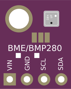
 Design with BME/BMP280 in Cirkit Designer
Introduction
The BME/BMP280 is a high-precision digital sensor designed to measure temperature, humidity, and atmospheric pressure. Manufactured by Bosch Sensortec, this sensor is widely used in applications requiring environmental monitoring, such as weather stations, drones, and Internet of Things (IoT) devices. The BME280 includes humidity sensing, while the BMP280 is a variant that measures only temperature and pressure. Both sensors are compact, energy-efficient, and communicate via I2C or SPI interfaces, making them ideal for integration into a variety of projects.
Explore Projects Built with BME/BMP280
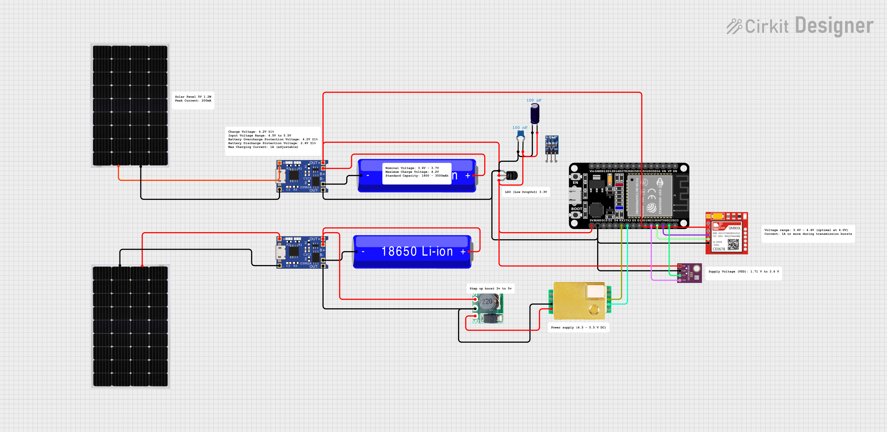 Open Project in Cirkit Designer
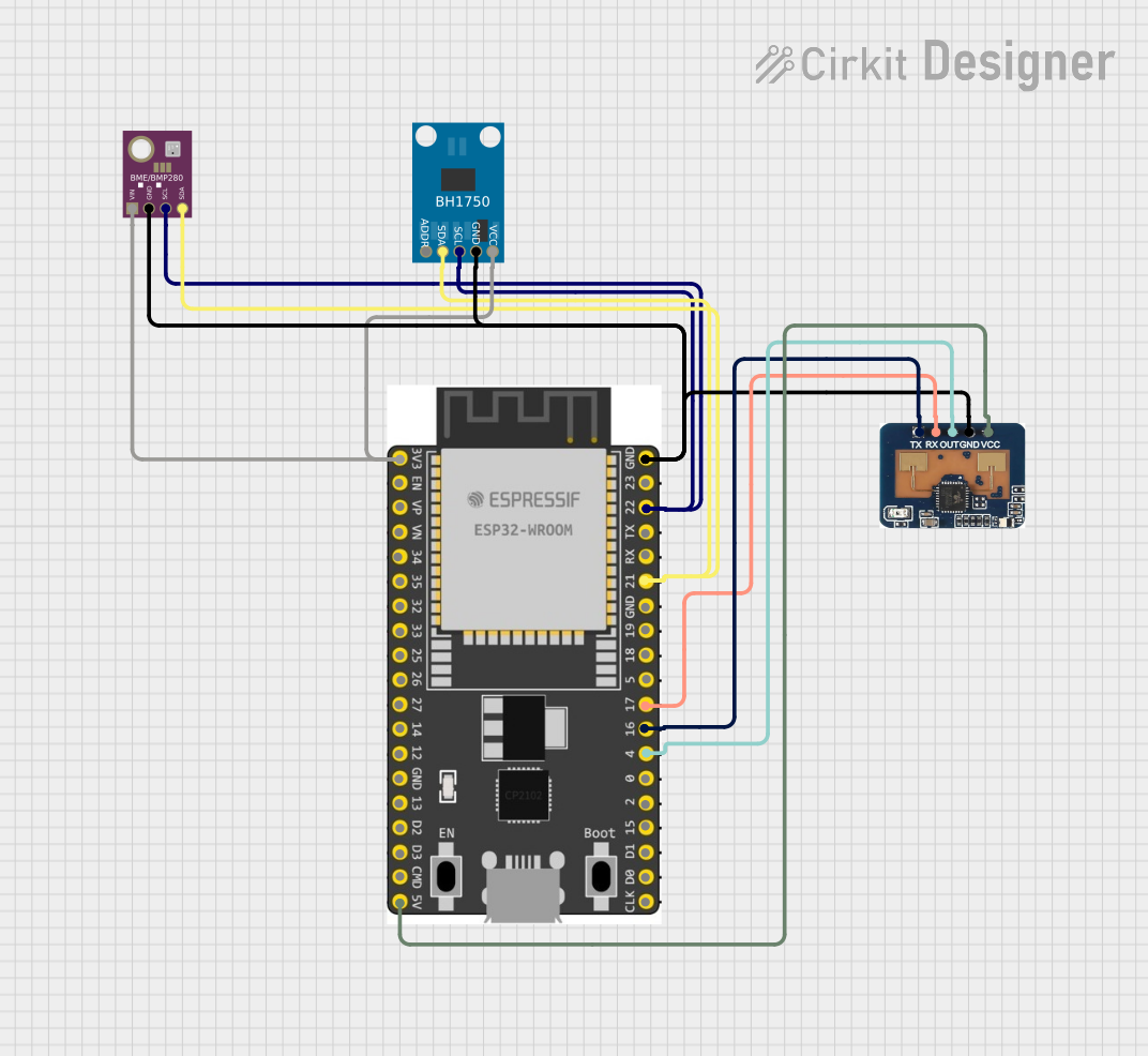 Open Project in Cirkit Designer
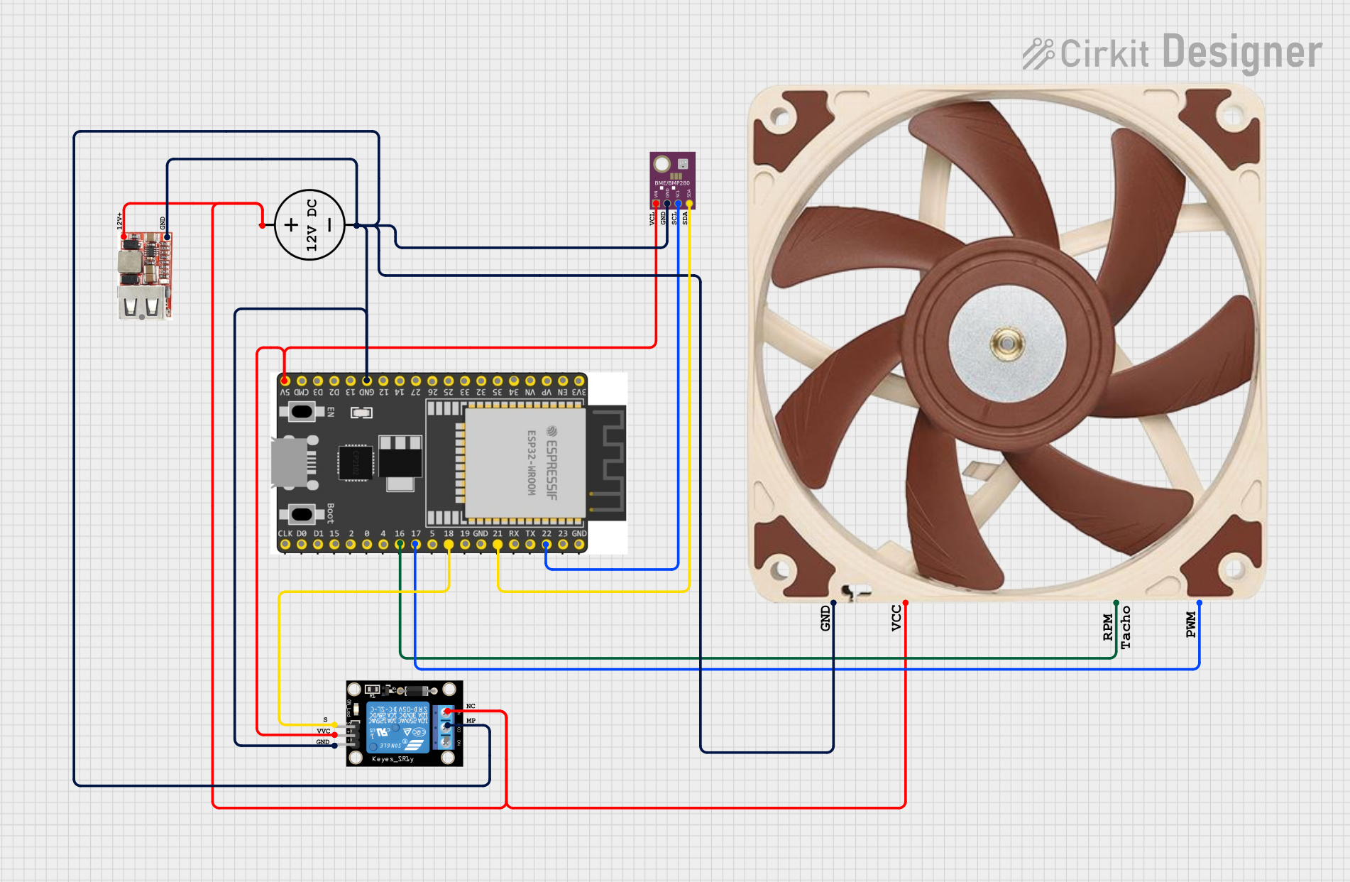 Open Project in Cirkit Designer
 Open Project in Cirkit Designer
Explore Projects Built with BME/BMP280
Open Project in Cirkit DesignerOpen Project in Cirkit DesignerOpen Project in Cirkit DesignerOpen Project in Cirkit DesignerTechnical Specifications
Key Specifications
| Parameter | BME280 | BMP280 |
|---|---|---|
| Supply Voltage | 1.71V to 3.6V | 1.71V to 3.6V |
| Operating Current | 2.7 µA (humidity + pressure + temp) | 2.7 µA (pressure + temp) |
| Temperature Range | -40°C to +85°C | -40°C to +85°C |
| Pressure Range | 300 hPa to 1100 hPa | 300 hPa to 1100 hPa |
| Humidity Range | 0% to 100% RH | Not applicable |
| Communication Protocols | I2C (up to 3.4 MHz), SPI (up to 10 MHz) | I2C (up to 3.4 MHz), SPI (up to 10 MHz) |
| Accuracy (Temperature) | ±1.0°C | ±1.0°C |
| Accuracy (Pressure) | ±1.0 hPa | ±1.0 hPa |
| Accuracy (Humidity) | ±3% RH | Not applicable |
Pin Configuration
The BME/BMP280 sensor typically comes in a breakout board format with the following pinout:
| Pin Name | Description |
|---|---|
| VIN | Power supply input (3.3V recommended) |
| GND | Ground |
| SCL | Serial Clock Line for I2C or SPI Clock |
| SDA | Serial Data Line for I2C or SPI Data |
| CSB | Chip Select for SPI (connect to GND for I2C) |
| SDO | I2C Address Selection or SPI Data Out |
I2C Address Selection
- Connect SDO to GND for I2C address
0x76. - Connect SDO to VIN for I2C address
0x77.
Usage Instructions
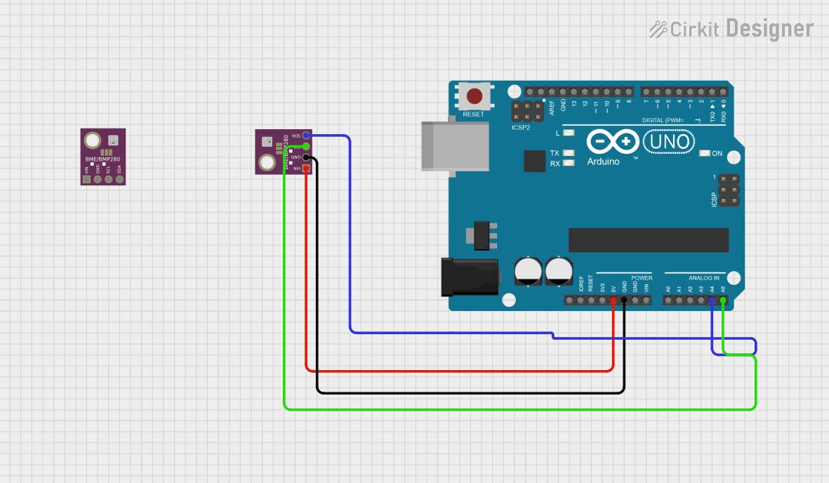
Connecting the BME/BMP280 to an Arduino UNO
Wiring:
- Connect the sensor's
VINpin to the Arduino's3.3Vpin. - Connect the
GNDpin to the Arduino'sGND. - Connect the
SCLpin to the Arduino'sA5pin (I2C clock line). - Connect the
SDApin to the Arduino'sA4pin (I2C data line). - Leave
CSBandSDOunconnected or configure them as needed.
- Connect the sensor's
Install Required Libraries:
- Install the Adafruit BME280 or BMP280 library from the Arduino Library Manager.
Example Code: Below is an example sketch for reading temperature, humidity, and pressure from the BME280 sensor:
#include <Wire.h>
#include <Adafruit_Sensor.h>
#include <Adafruit_BME280.h>

// Create an instance of the BME280 sensor
Adafruit_BME280 bme;

// Define I2C address (0x76 or 0x77 based on SDO connection)
#define BME280_I2C_ADDRESS 0x76

void setup() {
  Serial.begin(9600);
  while (!Serial); // Wait for serial monitor to open

  // Initialize the BME280 sensor
  if (!bme.begin(BME280_I2C_ADDRESS)) {
    Serial.println("Could not find a valid BME280 sensor, check wiring!");
    while (1); // Halt execution if sensor is not found
  }

  Serial.println("BME280 sensor initialized successfully!");
}

void loop() {
  // Read temperature, humidity, and pressure
  float temperature = bme.readTemperature();
  float humidity = bme.readHumidity();
  float pressure = bme.readPressure() / 100.0F; // Convert to hPa

  // Print readings to the Serial Monitor
  Serial.print("Temperature: ");
  Serial.print(temperature);
  Serial.println(" °C");

  Serial.print("Humidity: ");
  Serial.print(humidity);
  Serial.println(" %");

  Serial.print("Pressure: ");
  Serial.print(pressure);
  Serial.println(" hPa");

  delay(2000); // Wait 2 seconds before the next reading
}
Important Considerations
- Power Supply: Ensure the sensor is powered with 3.3V. Using 5V may damage the sensor.
- Pull-Up Resistors: If your breakout board does not include pull-up resistors on the I2C lines, add 4.7kΩ resistors between
SCL/SDAandVIN. - Altitude Calculation: The pressure reading can be used to calculate altitude using the barometric formula.
Troubleshooting and FAQs
Common Issues
Sensor Not Detected:
- Ensure the wiring is correct and matches the pinout.
- Verify the I2C address (
0x76or0x77) in the code. - Check for loose connections or damaged wires.
Incorrect Readings:
- Ensure the sensor is not exposed to extreme conditions outside its operating range.
- Avoid placing the sensor near heat sources or in areas with high airflow.
Arduino Freezes or Crashes:
- Ensure the sensor is properly powered with 3.3V.
- Check for conflicting I2C devices on the same bus.
FAQs
Q: Can I use the BME/BMP280 with a 5V microcontroller?
A: Yes, but you must use a logic level shifter to convert the 5V signals to 3.3V. Alternatively, some breakout boards include built-in level shifters.
Q: How do I switch between I2C and SPI modes?
A: For I2C, connect CSB to GND. For SPI, connect CSB to VIN and use the SDO pin for data output.
Q: What is the difference between the BME280 and BMP280?
A: The BME280 measures temperature, humidity, and pressure, while the BMP280 measures only temperature and pressure.
Q: Can I use the BME/BMP280 for altitude measurement?
A: Yes, the pressure readings can be used to calculate altitude using standard barometric formulas.