How to Use MyoWare Link Shield 2.0: Examples, Pinouts, and Specs
Introduction
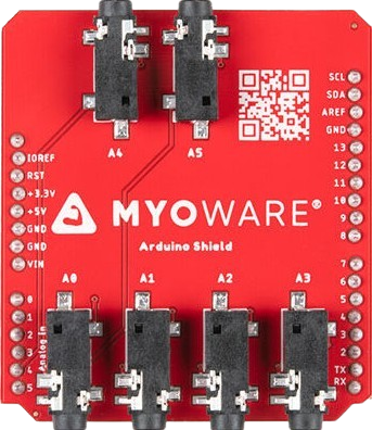
The MyoWare Link Shield 2.0 is an Arduino-compatible shield designed to simplify the integration of MyoWare muscle sensors into your projects. It provides a seamless way to collect and process electromyography (EMG) signals, making it ideal for applications in robotics, prosthetics, biofeedback systems, and other human-machine interface projects. By leveraging the MyoWare Link Shield 2.0, users can easily connect multiple MyoWare sensors and transmit EMG data for further analysis or control.
Explore Projects Built with MyoWare Link Shield 2.0
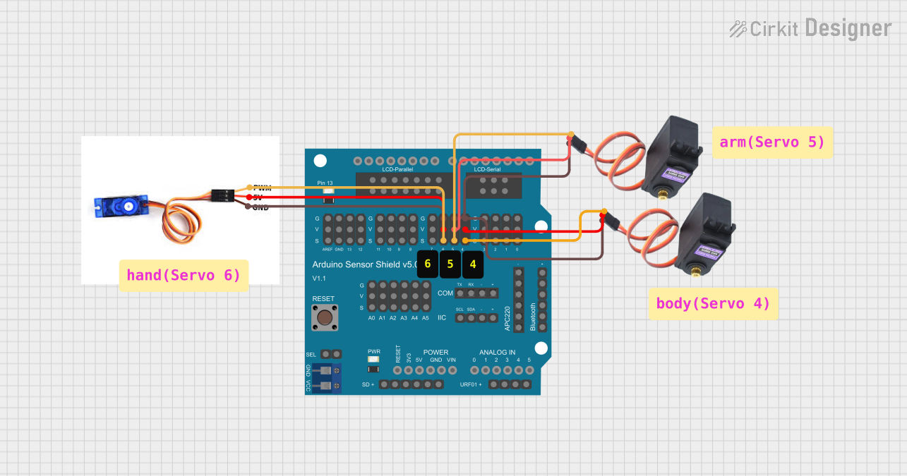
Explore Projects Built with MyoWare Link Shield 2.0
Common Applications and Use Cases
- Robotics: Control robotic arms or exoskeletons using muscle signals.
- Prosthetics: Enable intuitive control of prosthetic devices.
- Biofeedback Systems: Monitor and analyze muscle activity for medical or fitness purposes.
- Human-Machine Interfaces: Develop systems that respond to muscle movements for gaming or assistive technologies.
Technical Specifications
The MyoWare Link Shield 2.0 is designed to work seamlessly with MyoWare muscle sensors and Arduino boards. Below are the key technical details:
General Specifications
- Input Voltage: 3.3V or 5V (via Arduino power supply)
- Communication Interface: Serial (UART)
- Compatibility: Arduino Uno, Arduino Mega, and other Arduino-compatible boards
- Dimensions: 68.6mm x 53.3mm (standard Arduino shield size)
- Weight: ~20g
Pin Configuration and Descriptions
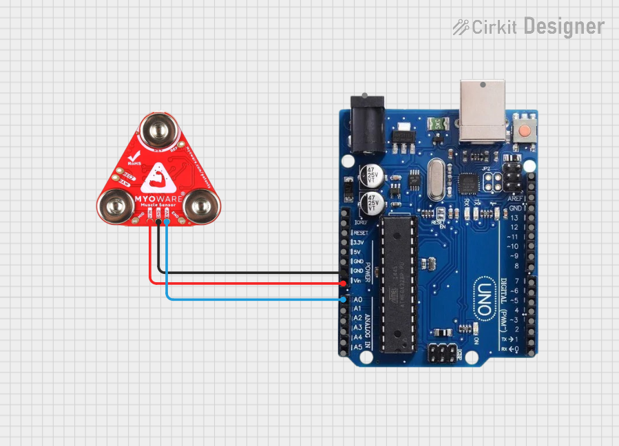
The MyoWare Link Shield 2.0 connects directly to the Arduino board via its standard shield headers. Below is the pin configuration:
| Pin | Name | Description |
|---|---|---|
| D0 | RX | Serial receive pin for UART communication. |
| D1 | TX | Serial transmit pin for UART communication. |
| A0 | EMG Signal | Analog input pin for receiving EMG signals from the MyoWare muscle sensor. |
| GND | Ground | Common ground connection for the shield and Arduino. |
| 3.3V | 3.3V Power | Power supply for the shield (optional, if not using 5V). |
| 5V | 5V Power | Power supply for the shield (default power source from Arduino). |
| SDA | I2C Data Line | Optional I2C data line for advanced communication (not commonly used). |
| SCL | I2C Clock Line | Optional I2C clock line for advanced communication (not commonly used). |
Usage Instructions
How to Use the MyoWare Link Shield 2.0 in a Circuit
- Attach the Shield: Place the MyoWare Link Shield 2.0 onto your Arduino board, ensuring the pins align correctly.
- Connect the MyoWare Sensor: Plug the MyoWare muscle sensor into the shield's designated input port.
- Power the System: Connect the Arduino to a power source (via USB or external power supply).
- Read EMG Data: Use the Arduino's analog input (A0) to read the EMG signal from the MyoWare sensor.
- Process the Data: Write Arduino code to process the EMG signal for your specific application.
Important Considerations and Best Practices
- Power Supply: Ensure the Arduino board is powered adequately to avoid signal instability.
- Signal Noise: Use proper grounding and shielding to minimize noise in the EMG signal.
- Sensor Placement: Place the MyoWare muscle sensor on clean, dry skin for optimal signal quality.
- Code Calibration: Calibrate your Arduino code to filter and interpret the EMG signal effectively.
Example Arduino Code
Below is an example of how to read and display EMG data from the MyoWare Link Shield 2.0 using an Arduino Uno:
// Example code for reading EMG data from MyoWare Link Shield 2.0
// Connect the MyoWare muscle sensor to the shield and read data on A0

const int emgPin = A0; // Analog pin connected to the EMG signal output

void setup() {
  Serial.begin(9600); // Initialize serial communication at 9600 baud
  pinMode(emgPin, INPUT); // Set the EMG pin as an input
}

void loop() {
  int emgValue = analogRead(emgPin); // Read the EMG signal from the sensor
  Serial.print("EMG Value: "); // Print a label for the EMG value
  Serial.println(emgValue); // Print the EMG value to the Serial Monitor
  delay(10); // Small delay to stabilize readings
}
Troubleshooting and FAQs
Common Issues and Solutions
No EMG Signal Detected
- Cause: Poor connection between the MyoWare sensor and the shield.
- Solution: Ensure the sensor is securely connected to the shield and placed correctly on the skin.
Signal Noise or Instability
- Cause: Electrical interference or improper grounding.
- Solution: Use shorter wires, ensure proper grounding, and avoid placing the sensor near high-power devices.
Arduino Not Communicating with Shield
- Cause: Incorrect pin configuration or faulty connections.
- Solution: Verify that the shield is properly seated on the Arduino and that the RX/TX pins are not being used by other devices.
Low Signal Amplitude
- Cause: Poor skin contact or dry skin.
- Solution: Clean the skin and ensure the sensor's electrodes are making good contact.
FAQs
Can I use the MyoWare Link Shield 2.0 with other microcontrollers?
- Yes, as long as the microcontroller supports UART or analog input, you can adapt the shield for use.
What is the maximum sampling rate for EMG signals?
- The sampling rate depends on the Arduino's ADC (typically 10-bit resolution at ~10kHz).
Can I connect multiple MyoWare sensors to the shield?
- Yes, but you will need to use additional analog input pins or multiplexers for multiple sensors.
Is the shield compatible with 3.3V Arduino boards?
- Yes, the shield supports both 3.3V and 5V logic levels.