Cirkit Designer Logo
Cirkit Designer
Your all-in-one circuit design IDE
Home / 
Component Documentation

How to Use RTC DS3231 Pi: Examples, Pinouts, and Specs

Image of RTC DS3231 Pi
Cirkit Designer LogoDesign with RTC DS3231 Pi in Cirkit Designer

Introduction

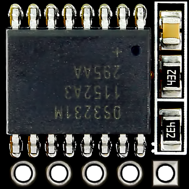
The RTC DS3231 Pi is a highly accurate real-time clock (RTC) module designed for timekeeping applications. Manufactured in China, this module integrates a temperature-compensated crystal oscillator (TCXO) and a battery backup, ensuring precise timekeeping even during power interruptions. The DS3231 is widely used in projects requiring accurate time and date tracking, such as data logging, alarms, and scheduling systems.

This module is particularly popular in Raspberry Pi and Arduino projects due to its ease of use and I2C communication interface.

Explore Projects Built with RTC DS3231 Pi

Use Cirkit Designer to design, explore, and prototype these projects online. Some projects support real-time simulation. Click "Open Project" to start designing instantly!
Raspberry Pi Zero W-Based Ultrasonic Distance Measurement with RTC Time-Stamping
Image of Water Logger: A project utilizing RTC DS3231 Pi in a practical application
This circuit integrates a Raspberry Pi Zero W with an HC-SR04 Ultrasonic Sensor and an RTC DS3231 Real-Time Clock module. The Raspberry Pi is configured to communicate with the RTC via I2C (using GPIO2 for SDA and GPIO3 for SCL) to keep track of real-time, and it controls the ultrasonic sensor (triggering via GPIO23 and receiving echo signals on GPIO24) for distance measurement purposes. Power is supplied to the sensor and RTC from the Raspberry Pi's 5V and 3.3V pins respectively, with common ground connections.
Cirkit Designer LogoOpen Project in Cirkit Designer
ESP32-Based Real-Time Clock Synchronization
Image of DS3231: A project utilizing RTC DS3231 Pi in a practical application
This circuit connects an ESP32 Devkit V1 microcontroller with an RTC DS3231 real-time clock module. The ESP32 provides power to the RTC and communicates with it via I2C, with D21 and D22 serving as the data (SDA) and clock (SCL) lines, respectively. The common ground (GND) ensures a reference point for the voltages, and the 3V3 pin from the ESP32 powers the RTC module.
Cirkit Designer LogoOpen Project in Cirkit Designer
ESP32-Based Real-Time Clock Synchronization
Image of RTC: A project utilizing RTC DS3231 Pi in a practical application
This circuit connects an ESP32 microcontroller to a DS3231 Real Time Clock (RTC) module. The ESP32's Vin and GND pins are connected to the VCC and GND pins of the DS3231, providing power to the RTC. The SCL and SDA pins of the DS3231 are connected to the D22 and D21 pins of the ESP32, respectively, enabling I2C communication between the microcontroller and the RTC module.
Cirkit Designer LogoOpen Project in Cirkit Designer
Raspberry Pi 3B Smart Home Automation with Relay Control and DHT11 Sensor
Image of Mycodo v1: A project utilizing RTC DS3231 Pi in a practical application
This circuit integrates a Raspberry Pi 3B with a DHT11 temperature and humidity sensor, a DS3231 RTC module, and a two-channel relay. The Raspberry Pi controls the relay channels and reads data from the DHT11 sensor and the RTC module via GPIO and I2C connections, respectively, enabling environmental monitoring and time-based control applications.
Cirkit Designer LogoOpen Project in Cirkit Designer

Explore Projects Built with RTC DS3231 Pi

Use Cirkit Designer to design, explore, and prototype these projects online. Some projects support real-time simulation. Click "Open Project" to start designing instantly!
Image of Water Logger: A project utilizing RTC DS3231 Pi in a practical application
Raspberry Pi Zero W-Based Ultrasonic Distance Measurement with RTC Time-Stamping
This circuit integrates a Raspberry Pi Zero W with an HC-SR04 Ultrasonic Sensor and an RTC DS3231 Real-Time Clock module. The Raspberry Pi is configured to communicate with the RTC via I2C (using GPIO2 for SDA and GPIO3 for SCL) to keep track of real-time, and it controls the ultrasonic sensor (triggering via GPIO23 and receiving echo signals on GPIO24) for distance measurement purposes. Power is supplied to the sensor and RTC from the Raspberry Pi's 5V and 3.3V pins respectively, with common ground connections.
Cirkit Designer LogoOpen Project in Cirkit Designer
Image of DS3231: A project utilizing RTC DS3231 Pi in a practical application
ESP32-Based Real-Time Clock Synchronization
This circuit connects an ESP32 Devkit V1 microcontroller with an RTC DS3231 real-time clock module. The ESP32 provides power to the RTC and communicates with it via I2C, with D21 and D22 serving as the data (SDA) and clock (SCL) lines, respectively. The common ground (GND) ensures a reference point for the voltages, and the 3V3 pin from the ESP32 powers the RTC module.
Cirkit Designer LogoOpen Project in Cirkit Designer
Image of RTC: A project utilizing RTC DS3231 Pi in a practical application
ESP32-Based Real-Time Clock Synchronization
This circuit connects an ESP32 microcontroller to a DS3231 Real Time Clock (RTC) module. The ESP32's Vin and GND pins are connected to the VCC and GND pins of the DS3231, providing power to the RTC. The SCL and SDA pins of the DS3231 are connected to the D22 and D21 pins of the ESP32, respectively, enabling I2C communication between the microcontroller and the RTC module.
Cirkit Designer LogoOpen Project in Cirkit Designer
Image of Mycodo v1: A project utilizing RTC DS3231 Pi in a practical application
Raspberry Pi 3B Smart Home Automation with Relay Control and DHT11 Sensor
This circuit integrates a Raspberry Pi 3B with a DHT11 temperature and humidity sensor, a DS3231 RTC module, and a two-channel relay. The Raspberry Pi controls the relay channels and reads data from the DHT11 sensor and the RTC module via GPIO and I2C connections, respectively, enabling environmental monitoring and time-based control applications.
Cirkit Designer LogoOpen Project in Cirkit Designer

Common Applications:

  • Data logging systems
  • Alarm clocks and timers
  • IoT devices requiring time synchronization
  • Scheduling and automation systems
  • Time-stamped data collection

Technical Specifications

The DS3231 Pi module is built for reliability and precision. Below are its key technical details:

Key Features:

  • Operating Voltage: 3.3V to 5.5V
  • Timekeeping Accuracy: ±2 ppm (±0.1728 seconds/day) from 0°C to +40°C
  • Backup Battery Support: CR2032 coin cell battery
  • Communication Protocol: I2C (Inter-Integrated Circuit)
  • Temperature Range: -40°C to +85°C
  • Memory: 32 bytes of non-volatile RAM for user data
  • Oscillator: Built-in temperature-compensated crystal oscillator (TCXO)

Pin Configuration:

The DS3231 Pi module typically has a 5-pin interface. Below is the pinout description:

Pin Name Description
1 GND Ground (0V reference)
2 VCC Power supply (3.3V to 5.5V)
3 SDA I2C data line
4 SCL I2C clock line
5 SQW/INT Square wave or interrupt output (optional)

Usage Instructions

The DS3231 Pi module is straightforward to use in a circuit. Below are the steps and best practices for integrating it into your project:

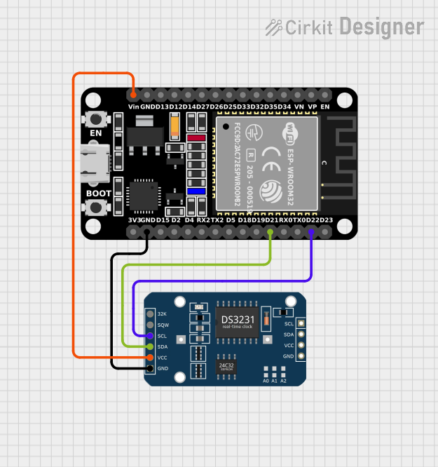
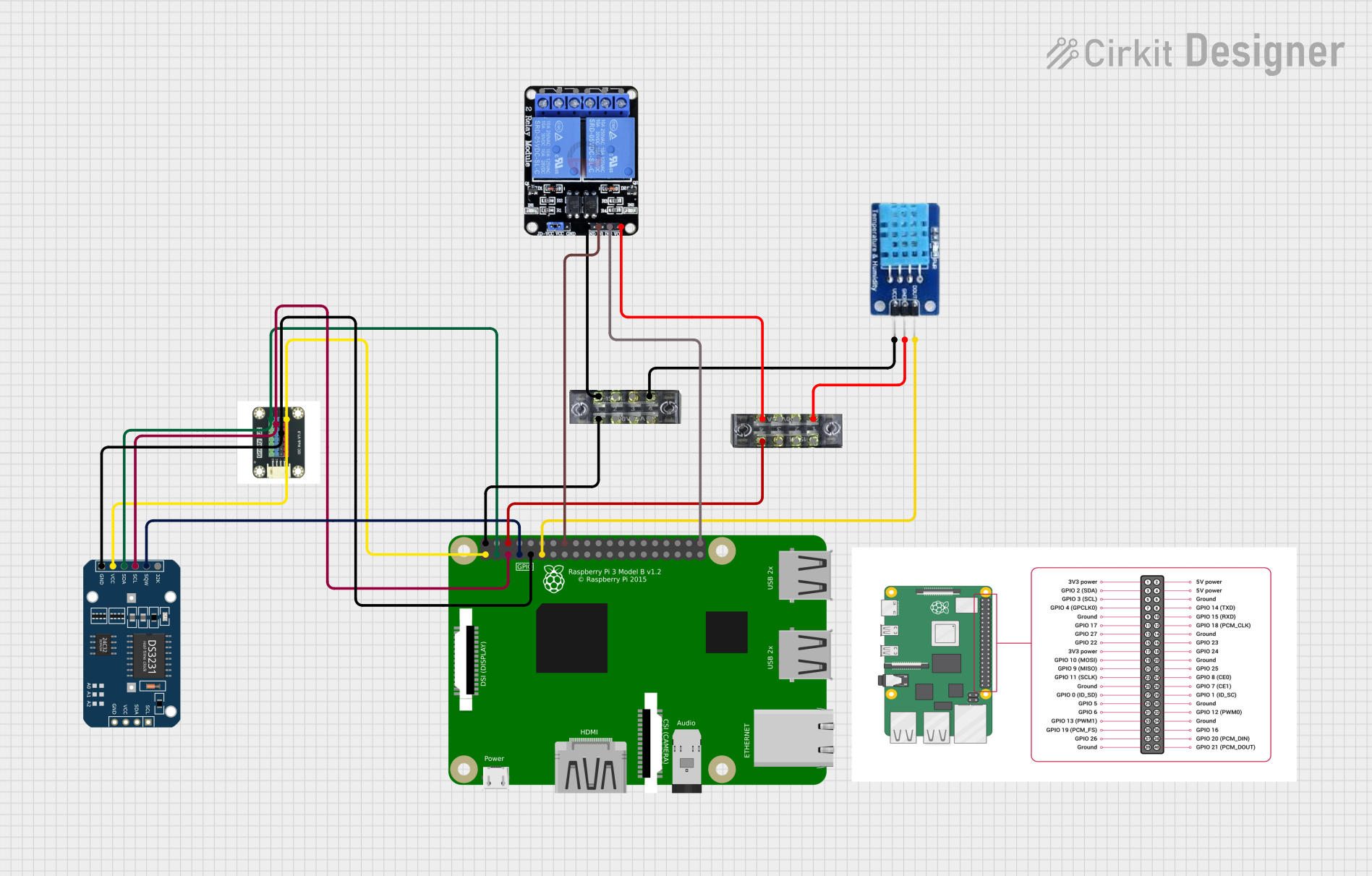
Connecting the DS3231 Pi to a Raspberry Pi or Arduino:

  1. Power Supply: Connect the VCC pin to a 3.3V or 5V power source and the GND pin to ground.
  2. I2C Communication:
    • Connect the SDA pin to the I2C data line of your microcontroller.
    • Connect the SCL pin to the I2C clock line of your microcontroller.
  3. Optional Output: If needed, connect the SQW/INT pin to a GPIO pin for square wave or interrupt functionality.

Example Code for Arduino UNO:

Below is an example of how to use the DS3231 Pi module with an Arduino UNO. This code sets the time and reads it back.

#include <Wire.h>
#include "RTClib.h" // Include the Adafruit RTC library

RTC_DS3231 rtc; // Create an RTC object

void setup() {
  Serial.begin(9600); // Initialize serial communication
  Wire.begin();       // Initialize I2C communication

  if (!rtc.begin()) {
    Serial.println("Couldn't find RTC. Check connections!");
    while (1); // Halt execution if RTC is not found
  }

  if (rtc.lostPower()) {
    Serial.println("RTC lost power, setting the time!");
    // Set the RTC to the current date and time
    rtc.adjust(DateTime(F(__DATE__), F(__TIME__)));
  }
}

void loop() {
  DateTime now = rtc.now(); // Get the current time

  // Print the current date and time to the serial monitor
  Serial.print(now.year(), DEC);
  Serial.print('/');
  Serial.print(now.month(), DEC);
  Serial.print('/');
  Serial.print(now.day(), DEC);
  Serial.print(" ");
  Serial.print(now.hour(), DEC);
  Serial.print(':');
  Serial.print(now.minute(), DEC);
  Serial.print(':');
  Serial.print(now.second(), DEC);
  Serial.println();

  delay(1000); // Wait for 1 second before updating
}

Best Practices:

  • Use a CR2032 battery to ensure the RTC keeps time during power outages.
  • Avoid powering the module with voltages outside the 3.3V to 5.5V range to prevent damage.
  • Use pull-up resistors (typically 4.7kΩ) on the SDA and SCL lines if your microcontroller does not have internal pull-ups enabled.

Troubleshooting and FAQs

Common Issues:

  1. RTC Not Detected:

    • Cause: Incorrect wiring or I2C address mismatch.
    • Solution: Double-check the connections and ensure the SDA and SCL lines are correctly connected. The default I2C address for the DS3231 is 0x68.
  2. Incorrect Time Displayed:

    • Cause: RTC lost power or was not initialized properly.
    • Solution: Use the rtc.adjust() function to set the correct time.
  3. No Output on Serial Monitor:

    • Cause: Serial communication not initialized or incorrect baud rate.
    • Solution: Ensure Serial.begin(9600); matches the baud rate in the serial monitor.
  4. Square Wave/Interrupt Not Working:

    • Cause: SQW/INT pin not configured.
    • Solution: Use the appropriate library functions to enable and configure the square wave output.

FAQs:

Q: Can the DS3231 Pi module work without a backup battery?
A: Yes, but it will lose timekeeping functionality when power is removed. A CR2032 battery is recommended for uninterrupted operation.

Q: What is the default I2C address of the DS3231?
A: The default I2C address is 0x68.

Q: Can I use the DS3231 Pi module with a 3.3V microcontroller?
A: Yes, the module supports both 3.3V and 5V logic levels, making it compatible with a wide range of microcontrollers.

Q: How accurate is the DS3231 module?
A: The DS3231 is highly accurate, with a timekeeping accuracy of ±2 ppm from 0°C to +40°C.

By following this documentation, you can effectively integrate the DS3231 Pi module into your projects and troubleshoot common issues with ease.