How to Use ESP-32 DEVKIT-V1 Expansion Board: Examples, Pinouts, and Specs
Introduction
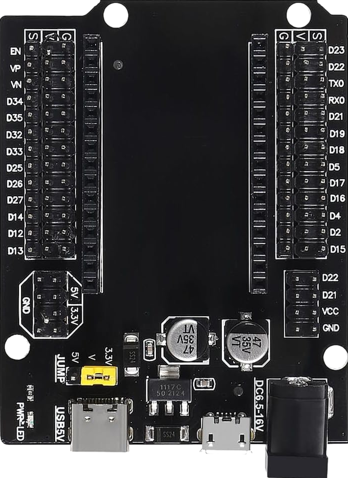
The ESP-32 DEVKIT-V1 Expansion Board, manufactured by Espressif, is a versatile development board featuring the ESP32 microcontroller. This board is equipped with Wi-Fi and Bluetooth capabilities, making it ideal for Internet of Things (IoT) projects and rapid prototyping. The ESP32 microcontroller offers a rich set of features, including multiple GPIO pins, ADCs, DACs, UART, SPI, I2C, and more, providing a robust platform for a wide range of applications.
Explore Projects Built with ESP-32 DEVKIT-V1 Expansion Board


Explore Projects Built with ESP-32 DEVKIT-V1 Expansion Board
Common Applications and Use Cases
- IoT Devices: Smart home devices, environmental monitoring, and industrial IoT applications.
- Prototyping: Rapid development and testing of new ideas and projects.
- Wireless Communication: Projects requiring Wi-Fi and Bluetooth connectivity.
- Embedded Systems: Integration into larger systems requiring microcontroller functionality.
Technical Specifications
Key Technical Details
| Specification | Value |
|---|---|
| Microcontroller | ESP32 |
| Operating Voltage | 3.3V |
| Input Voltage | 5V (via USB) |
| Digital I/O Pins | 34 |
| Analog Input Pins | 16 (12-bit ADC) |
| Analog Output Pins | 2 (8-bit DAC) |
| Flash Memory | 4MB |
| SRAM | 520KB |
| Communication | Wi-Fi 802.11 b/g/n, Bluetooth v4.2 BR/EDR/LE |
| Interfaces | UART, SPI, I2C, I2S, PWM, GPIO |
| Dimensions | 54mm x 28mm |
Pin Configuration and Descriptions
| Pin Number | Pin Name | Description |
|---|---|---|
| 1 | EN | Enable (Active High) |
| 2 | IO36 | GPIO36, ADC1_CH0 |
| 3 | IO39 | GPIO39, ADC1_CH3 |
| 4 | IO34 | GPIO34, ADC1_CH6 |
| 5 | IO35 | GPIO35, ADC1_CH7 |
| 6 | IO32 | GPIO32, ADC1_CH4, Touch9 |
| 7 | IO33 | GPIO33, ADC1_CH5, Touch8 |
| 8 | IO25 | GPIO25, DAC1, ADC2_CH8 |
| 9 | IO26 | GPIO26, DAC2, ADC2_CH9 |
| 10 | IO27 | GPIO27, ADC2_CH7, Touch7 |
| 11 | IO14 | GPIO14, ADC2_CH6, Touch6, HSPI_CLK |
| 12 | IO12 | GPIO12, ADC2_CH5, Touch5, HSPI_MISO |
| 13 | GND | Ground |
| 14 | IO13 | GPIO13, ADC2_CH4, Touch4, HSPI_MOSI |
| 15 | IO9 | GPIO9, ADC2_CH2, Touch2 |
| 16 | IO10 | GPIO10, ADC2_CH3, Touch3 |
| 17 | IO11 | GPIO11, ADC2_CH1, Touch1 |
| 18 | IO6 | GPIO6, ADC2_CH0, Touch0 |
| 19 | IO7 | GPIO7, ADC2_CH10, Touch10 |
| 20 | IO8 | GPIO8, ADC2_CH11, Touch11 |
| 21 | IO15 | GPIO15, ADC2_CH12, Touch12 |
| 22 | IO2 | GPIO2, ADC2_CH13, Touch13 |
| 23 | IO0 | GPIO0, ADC2_CH14, Touch14 |
| 24 | IO4 | GPIO4, ADC2_CH15, Touch15 |
| 25 | IO16 | GPIO16, ADC2_CH16, Touch16 |
| 26 | IO17 | GPIO17, ADC2_CH17, Touch17 |
| 27 | IO18 | GPIO18, ADC2_CH18, Touch18 |
| 28 | IO19 | GPIO19, ADC2_CH19, Touch19 |
| 29 | IO21 | GPIO21, ADC2_CH20, Touch20 |
| 30 | IO22 | GPIO22, ADC2_CH21, Touch21 |
| 31 | IO23 | GPIO23, ADC2_CH22, Touch22 |
| 32 | IO5 | GPIO5, ADC2_CH23, Touch23 |
| 33 | IO3 | GPIO3, ADC2_CH24, Touch24 |
| 34 | IO1 | GPIO1, ADC2_CH25, Touch25 |
| 35 | IO30 | GPIO30, ADC2_CH26, Touch26 |
| 36 | IO31 | GPIO31, ADC2_CH27, Touch27 |
| 37 | IO28 | GPIO28, ADC2_CH28, Touch28 |
| 38 | IO29 | GPIO29, ADC2_CH29, Touch29 |
| 39 | IO20 | GPIO20, ADC2_CH30, Touch30 |
| 40 | IO24 | GPIO24, ADC2_CH31, Touch31 |
Usage Instructions
How to Use the Component in a Circuit
Powering the Board:
- Connect the board to your computer using a USB cable. This will provide the necessary 5V input voltage.
- Alternatively, you can power the board using an external 3.3V power supply connected to the 3V3 pin.
Programming the Board:
- Install the Arduino IDE and add the ESP32 board support via the Board Manager.
- Select "ESP32 Dev Module" from the Tools > Board menu.
- Connect the board to your computer and select the appropriate COM port.
- Write your code and upload it to the board.
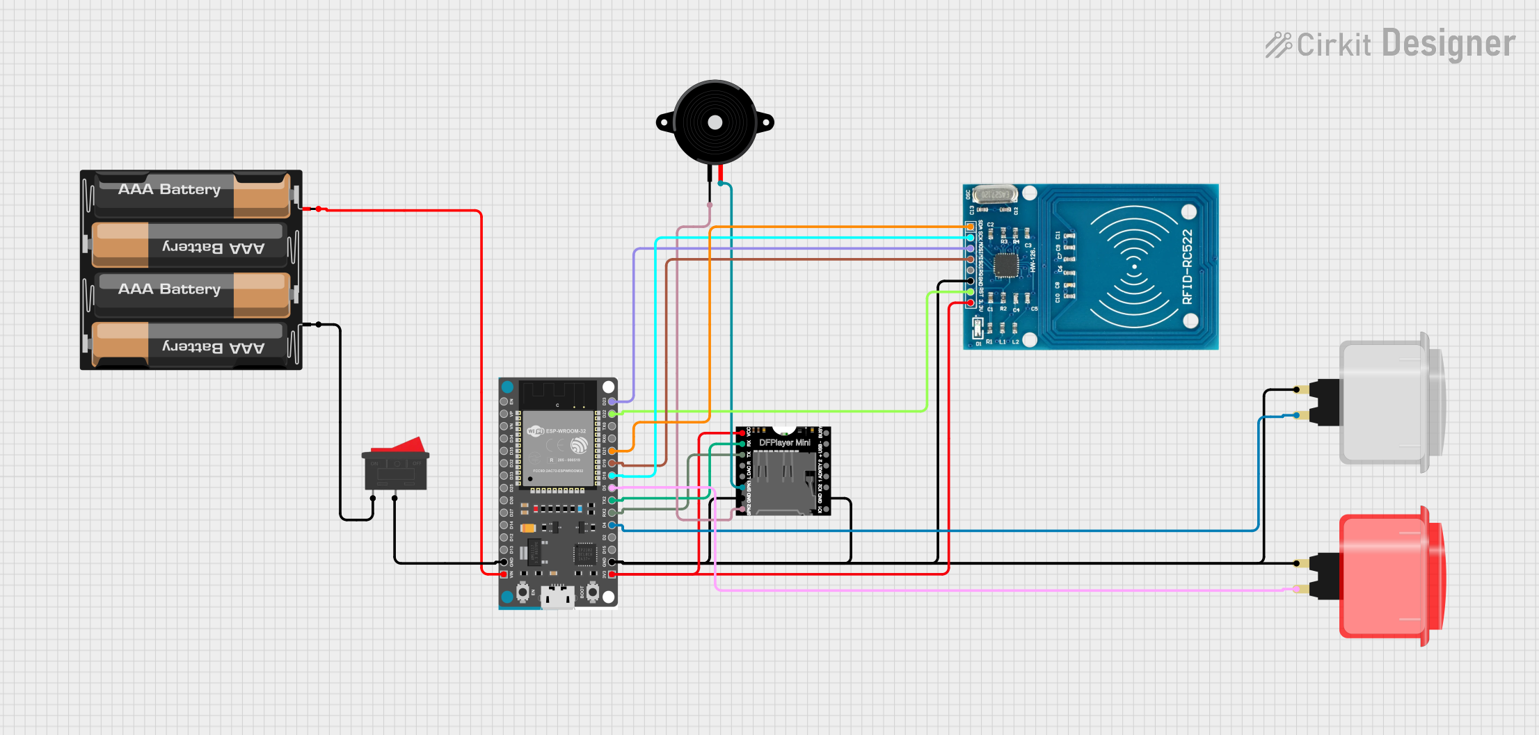
Connecting Peripherals:
- Use the GPIO pins to connect sensors, actuators, and other peripherals.
- Ensure that the voltage levels of the peripherals are compatible with the 3.3V logic level of the ESP32.
Important Considerations and Best Practices
- Voltage Levels: The ESP32 operates at 3.3V. Ensure that all connected peripherals are compatible with this voltage level to avoid damage.
- Pin Multiplexing: Some pins have multiple functions (e.g., GPIO, ADC, DAC). Be mindful of the pin configuration to avoid conflicts.
- Power Consumption: The ESP32 can consume significant power, especially when Wi-Fi and Bluetooth are active. Consider power management strategies for battery-powered applications.
- Antenna Placement: For optimal wireless performance, ensure that the onboard antenna is not obstructed by metal objects or other components.
Example Code
Here is an example code to connect the ESP-32 DEVKIT-V1 to an Arduino UNO and read data from a DHT11 temperature and humidity sensor:
#include <DHT.h>

#define DHTPIN 4     // Pin connected to the DHT11 sensor
#define DHTTYPE DHT11   // DHT 11

DHT dht(DHTPIN, DHTTYPE);

void setup() {
  Serial.begin(115200);
  dht.begin();
}

void loop() {
  delay(2000);  // Wait a few seconds between measurements

  float h = dht.readHumidity();
  float t = dht.readTemperature();

  // Check if any reads failed and exit early (to try again).
  if (isnan(h) || isnan(t)) {
    Serial.println("Failed to read from DHT sensor!");
    return;
  }

  Serial.print("Humidity: ");
  Serial.print(h);
  Serial.print(" %\t");
  Serial.print("Temperature: ");
  Serial.print(t);
  Serial.println(" *C ");
}
Troubleshooting and FAQs
Common Issues Users Might Face
Board Not Detected:
- Ensure the USB cable is properly connected.
- Check if the correct COM port is selected in the Arduino IDE.
- Try using a different USB cable or port.
Upload Failures:
- Press and hold the "BOOT" button on the board while uploading the code.
- Ensure the correct board and COM port are selected in the Arduino IDE.
Wi-Fi Connection Issues:
- Verify the SSID and password are correct.
- Ensure the Wi-Fi network is within range and not experiencing interference.
Solutions and Tips for Troubleshooting
- Reset the Board: Press the "EN" button to reset the board if it becomes unresponsive.
- Check Power Supply: Ensure the board is receiving adequate power, especially when using external peripherals.
- Update Drivers: Ensure that the USB-to-serial drivers are up to date on your computer.
By following this documentation, users should be able to effectively utilize the ESP-32 DEVKIT-V1 Expansion Board in