How to Use SparkFun 2D Barcode Scanner Breakout - DE2120: Examples, Pinouts, and Specs
Introduction
The SparkFun 2D Barcode Scanner Breakout - DE2120 is a compact and versatile module designed to interface with 2D barcode scanners. It enables seamless integration into projects requiring the scanning of QR codes, Data Matrix codes, and other 1D/2D barcodes. This breakout board is ideal for applications in retail, inventory management, access control, and embedded systems where barcode scanning is essential.
With its small form factor and straightforward connectivity options, the DE2120 breakout board simplifies the process of adding barcode scanning functionality to your projects. It supports both UART and USB communication, making it compatible with a wide range of microcontrollers and systems.
Explore Projects Built with SparkFun 2D Barcode Scanner Breakout - DE2120
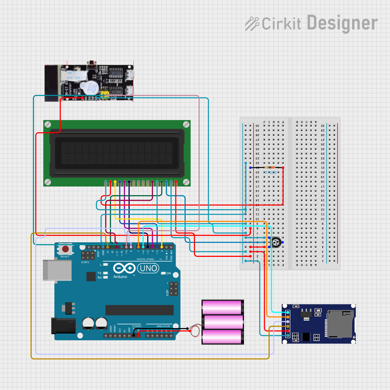

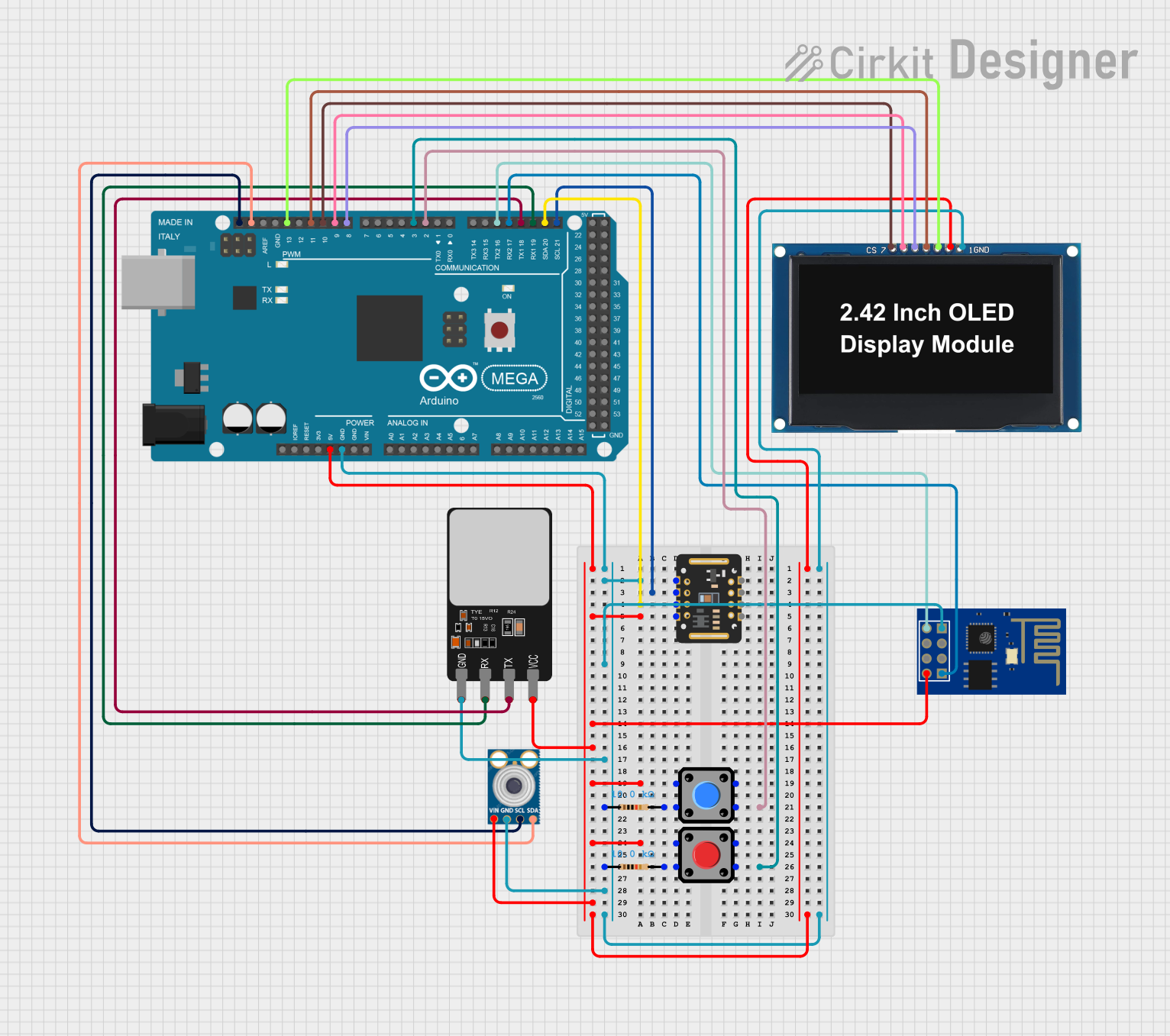

Explore Projects Built with SparkFun 2D Barcode Scanner Breakout - DE2120
Technical Specifications
Key Technical Details
- Manufacturer: SparkFun
- Part Number: DE2120
- Input Voltage: 3.3V to 6V DC
- Communication Interfaces: UART (3.3V logic) and USB
- Scan Rate: Up to 100 scans per second
- Supported Barcode Types:
- 1D: Code 128, Code 39, EAN-13, UPC-A, etc.
- 2D: QR Code, Data Matrix, PDF417, etc.
- Operating Temperature: -20°C to 60°C
- Dimensions: 25.4mm x 25.4mm (1" x 1")
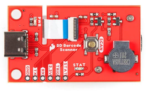
Pin Configuration and Descriptions
The DE2120 breakout board features a 6-pin header for UART communication and a micro-USB connector for USB communication. Below is the pinout for the 6-pin header:
| Pin | Name | Description |
|---|---|---|
| 1 | VCC | Power input (3.3V to 6V DC) |
| 2 | GND | Ground |
| 3 | TXD | UART Transmit (3.3V logic) |
| 4 | RXD | UART Receive (3.3V logic) |
| 5 | CTS | Clear to Send (optional, for UART flow control) |
| 6 | RTS | Request to Send (optional, for UART flow control) |
Usage Instructions
How to Use the Component in a Circuit
Powering the Module:
- Connect the VCC pin to a 3.3V to 6V DC power source.
- Connect the GND pin to the ground of your circuit.
Communication Setup:
- For UART communication, connect the TXD pin of the DE2120 to the RX pin of your microcontroller, and the RXD pin of the DE2120 to the TX pin of your microcontroller.
- Optionally, connect the CTS and RTS pins if your application requires UART flow control.
- For USB communication, simply connect the breakout board to your system using a micro-USB cable.
Barcode Scanning:
- Once powered and connected, the DE2120 will automatically begin scanning when a barcode is presented in its field of view.
- The scanned data will be transmitted via the selected communication interface (UART or USB).
Important Considerations and Best Practices
- Ensure that the module is powered within the specified voltage range (3.3V to 6V) to avoid damage.
- Use a level shifter if interfacing the UART pins with a 5V logic microcontroller.
- Maintain a clear line of sight between the scanner and the barcode for optimal performance.
- Avoid exposing the module to direct sunlight or reflective surfaces, as these may interfere with scanning accuracy.
Example: Connecting to an Arduino UNO
Below is an example of how to connect the DE2120 to an Arduino UNO using UART communication:
Wiring
| DE2120 Pin | Arduino UNO Pin |
|---|---|
| VCC | 5V |
| GND | GND |
| TXD | Pin 10 (RX) |
| RXD | Pin 11 (TX) |
Arduino Code
#include <SoftwareSerial.h>

// Define RX and TX pins for SoftwareSerial
SoftwareSerial barcodeScanner(10, 11); // RX = Pin 10, TX = Pin 11

void setup() {
  Serial.begin(9600); // Initialize Serial Monitor
  barcodeScanner.begin(9600); // Initialize barcode scanner communication

  Serial.println("SparkFun DE2120 Barcode Scanner Example");
  Serial.println("Present a barcode to the scanner...");
}

void loop() {
  // Check if data is available from the barcode scanner
  if (barcodeScanner.available()) {
    String barcodeData = "";

    // Read all available data from the scanner
    while (barcodeScanner.available()) {
      char c = barcodeScanner.read();
      barcodeData += c;
    }

    // Print the scanned barcode data to the Serial Monitor
    Serial.println("Scanned Data: " + barcodeData);
  }
}
Troubleshooting and FAQs
Common Issues and Solutions
No Data Received from the Scanner:
- Ensure that the module is powered correctly and the connections are secure.
- Verify that the UART baud rate matches the default setting of 9600 bps.
Scanner Fails to Detect Barcodes:
- Check that the barcode is within the scanner's field of view and is not damaged.
- Ensure proper lighting conditions and avoid reflective surfaces.
Communication Issues with Arduino:
- Confirm that the RX and TX pins are correctly connected.
- If using SoftwareSerial, ensure no conflicts with other libraries or pins.
FAQs
Can the DE2120 scan barcodes on a screen?
Yes, the DE2120 can scan barcodes displayed on screens, such as smartphones or tablets.What is the maximum scanning distance?
The effective scanning distance depends on the barcode size and type but typically ranges from 5cm to 30cm.Can I change the default UART baud rate?
Yes, the baud rate can be configured using specific commands sent to the module. Refer to the manufacturer's datasheet for details.Is the DE2120 compatible with Raspberry Pi?
Yes, the DE2120 can be connected to a Raspberry Pi via UART or USB.
This concludes the documentation for the SparkFun 2D Barcode Scanner Breakout - DE2120. For additional support, refer to the official SparkFun resources or community forums.