How to Use Ceramic Resonator (3-pin): Examples, Pinouts, and Specs

Introduction
A Ceramic Resonator is an electronic component utilized to generate stable clock signals for microcontrollers and other digital integrated circuits. It is a cost-effective alternative to quartz crystals and offers a compact solution for applications where precise timing is less critical. Ceramic resonators are widely used in consumer electronics, automotive systems, and various other embedded systems.
Explore Projects Built with Ceramic Resonator (3-pin)
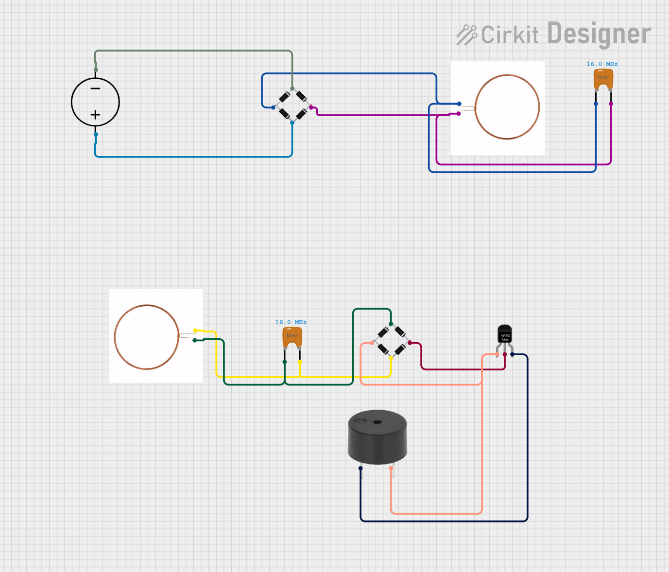

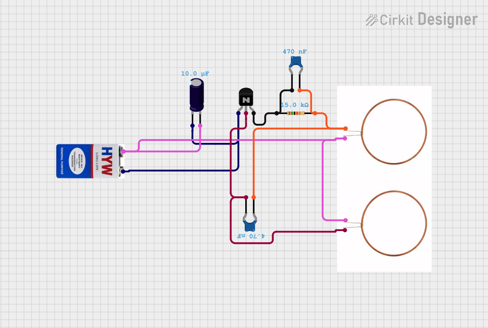
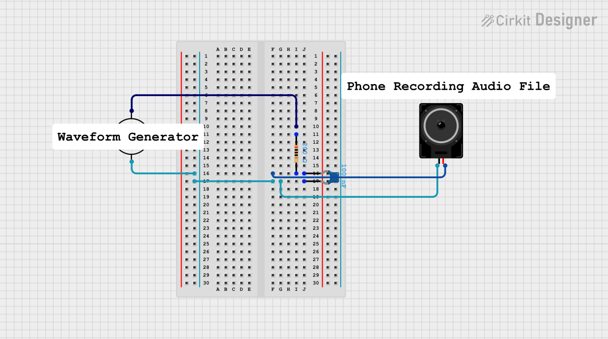
Explore Projects Built with Ceramic Resonator (3-pin)
Common Applications and Use Cases
- Microcontroller clock source
- Consumer electronics (e.g., toys, remote controls)
- Automotive electronics
- Timing generation in non-critical applications
Technical Specifications
Key Technical Details
- Nominal Frequency: Typically ranges from 400 kHz to 16 MHz
- Frequency Tolerance: ±0.5% to ±0.3%
- Operating Temperature Range: -40°C to +85°C
- Load Capacitance: Built-in, usually around 15 pF to 30 pF per pin
- Drive Level: Typically around 1 mW
Pin Configuration and Descriptions
| Pin Number | Name | Description |
|---|---|---|
| 1 | OUT | Output of the oscillating frequency |
| 2 | GND | Ground connection |
| 3 | Vcc | Power supply (typically 5V) |
Usage Instructions
How to Use the Component in a Circuit
- Power Supply: Connect pin 3 (Vcc) to the positive supply voltage, typically 5V.
- Ground: Connect pin 2 (GND) to the circuit's ground.
- Output Connection: Connect pin 1 (OUT) to the clock input pin of the microcontroller or digital IC.
Important Considerations and Best Practices
- Ensure that the resonator's frequency matches the requirements of the microcontroller or digital IC.
- Keep the trace lengths between the resonator and the microcontroller as short as possible to minimize noise and interference.
- Avoid placing the resonator near high-temperature components or heat sources to prevent frequency drift.
- If the circuit is sensitive to timing accuracy, consider using a quartz crystal instead of a ceramic resonator.
Example Code for Arduino UNO
// Example code to set up an external ceramic resonator with an Arduino UNO

void setup() {
  // Assuming the resonator is connected to the appropriate XTAL pins on the MCU
  // No specific code is needed to use the resonator as the clock source.
  // The microcontroller will automatically use the external clock source if present.
}

void loop() {
  // Your code here
}
Note: The Arduino UNO typically uses a quartz crystal for its clock source. To use a ceramic resonator, you would need to modify the board or use a custom microcontroller setup that allows for an external clock source.
Troubleshooting and FAQs
Common Issues Users Might Face
- Inaccurate Timing: If the timing seems off, check the resonator's frequency and ensure it matches the microcontroller's requirements.
- No Oscillation: Ensure the resonator is properly powered and grounded. Also, check for any soldering issues or shorts.
Solutions and Tips for Troubleshooting
- Verify the connections and solder joints between the resonator and the microcontroller.
- Measure the voltage across the resonator to ensure it is receiving power.
- Use an oscilloscope to check the output pin for a stable oscillating signal.
FAQs
Q: Can I replace a quartz crystal with a ceramic resonator directly? A: While both components serve a similar function, they are not always directly interchangeable due to differences in load capacitance and stability. Check the microcontroller's datasheet for compatibility.
Q: How does temperature affect a ceramic resonator? A: Temperature variations can cause frequency drift in ceramic resonators. They are less stable compared to quartz crystals in this regard.
Q: What is the advantage of using a ceramic resonator over a quartz crystal? A: Ceramic resonators are generally less expensive and smaller in size, making them suitable for cost-sensitive and space-constrained applications where high precision is not critical.