How to Use SERVO: Examples, Pinouts, and Specs
Introduction
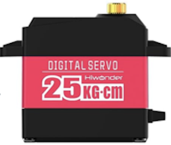
A servo is a rotary actuator that allows for precise control of angular position, velocity, and acceleration. It consists of a motor coupled to a sensor for position feedback, along with a control circuit. Servos are widely used in robotics, automation, remote-controlled vehicles, and industrial machinery due to their ability to provide accurate and repeatable motion.
Explore Projects Built with SERVO

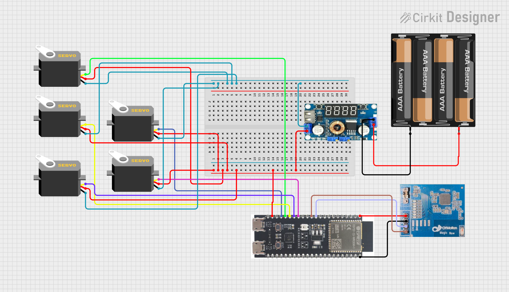

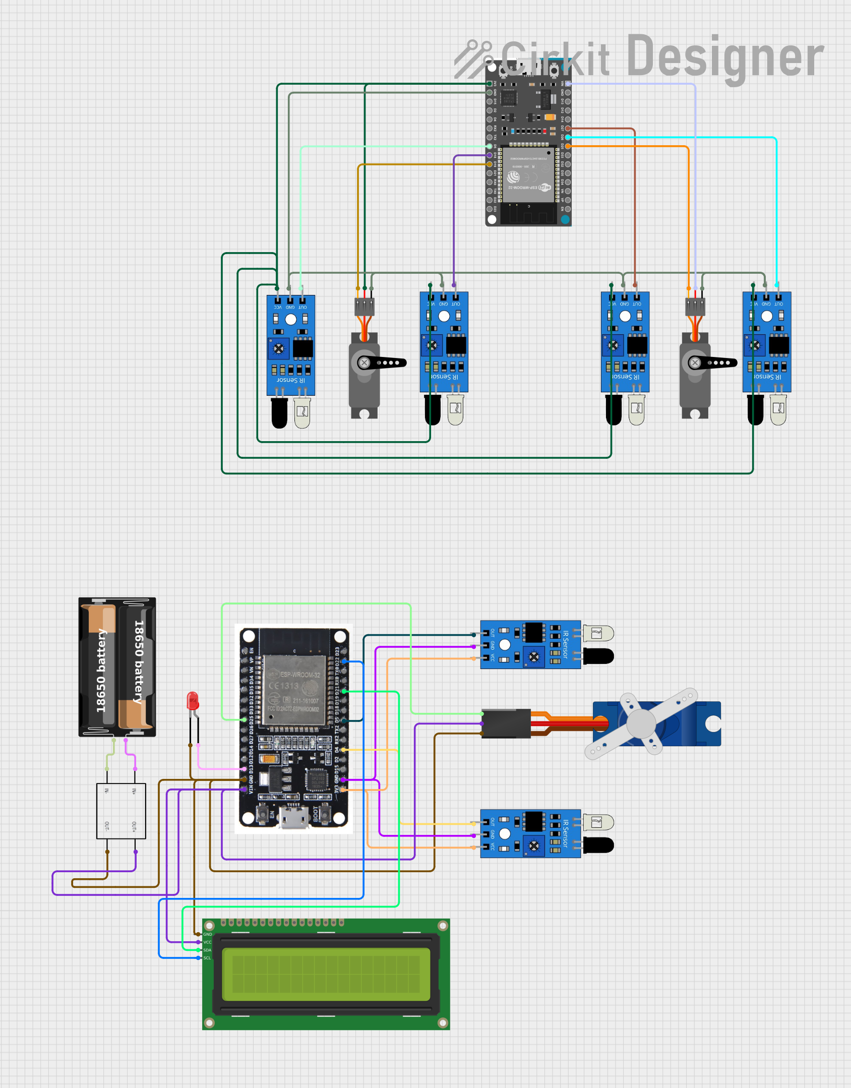
Explore Projects Built with SERVO
Common Applications and Use Cases
- Robotics: For controlling robotic arms, grippers, and joints.
- RC Vehicles: Steering and throttle control in remote-controlled cars, boats, and planes.
- Automation: Used in conveyor systems, pick-and-place machines, and other automated equipment.
- DIY Projects: Popular in hobbyist projects involving Arduino and Raspberry Pi.
- Camera Gimbals: For stabilizing and controlling camera angles.
Technical Specifications
Below are the general technical specifications for a standard hobby servo. Note that specifications may vary depending on the specific model and manufacturer.
Key Technical Details
- Operating Voltage: 4.8V to 6.0V (typical range)
- Current Draw: 10mA to 100mA (idle), up to 1A (under load)
- Torque: 1.5 kg-cm to 20 kg-cm (varies by model)
- Rotation Range: Typically 0° to 180° (some models support 360° continuous rotation)
- Control Signal: Pulse Width Modulation (PWM)
- Pulse width: 1ms (0°), 1.5ms (90°), 2ms (180°)
- Frequency: 50Hz (20ms period)
Pin Configuration and Descriptions
The servo typically has three wires for connection:
| Pin Name | Wire Color (Common) | Description |
|---|---|---|
| VCC | Red | Power supply (4.8V to 6.0V) |
| GND | Black/Brown | Ground |
| Signal | Yellow/White/Orange | PWM control signal |
Usage Instructions
How to Use the Servo in a Circuit
- Power the Servo: Connect the VCC pin to a 5V power source and the GND pin to ground. Ensure the power supply can handle the current draw of the servo, especially under load.
- Control Signal: Connect the Signal pin to a microcontroller (e.g., Arduino) or a dedicated servo controller. Use a PWM signal to control the servo's position.
- Position Control: Adjust the pulse width of the PWM signal to set the desired angle. For example:
- 1ms pulse width: 0° position
- 1.5ms pulse width: 90° position
- 2ms pulse width: 180° position
Important Considerations and Best Practices
- Power Supply: Use a separate power supply for the servo if it draws significant current, as powering it directly from a microcontroller may cause instability.
- Avoid Overloading: Do not exceed the torque rating of the servo to prevent damage.
- Signal Stability: Ensure the PWM signal is stable and within the specified frequency range (typically 50Hz).
- Mechanical Limits: Avoid forcing the servo beyond its physical rotation limits to prevent gear damage.
Example: Controlling a Servo with Arduino UNO
Below is an example code to control a servo using an Arduino UNO and the Servo library.
#include <Servo.h> // Include the Servo library

Servo myServo; // Create a Servo object

void setup() {
  myServo.attach(9); // Attach the servo to pin 9 on the Arduino
}

void loop() {
  myServo.write(0); // Move the servo to 0 degrees
  delay(1000);      // Wait for 1 second

  myServo.write(90); // Move the servo to 90 degrees
  delay(1000);       // Wait for 1 second

  myServo.write(180); // Move the servo to 180 degrees
  delay(1000);        // Wait for 1 second
}
Notes on the Code
- The
Servolibrary simplifies the process of generating PWM signals for servo control. - The
myServo.attach(9)function links the servo to pin 9 on the Arduino. - The
myServo.write(angle)function sets the servo to a specific angle (0° to 180°).
Troubleshooting and FAQs
Common Issues and Solutions
Servo Not Moving
- Cause: Insufficient power supply or incorrect wiring.
- Solution: Check the power source and ensure proper connections to VCC, GND, and Signal pins.
Jittery or Erratic Movement
- Cause: Unstable PWM signal or electrical noise.
- Solution: Use a decoupling capacitor across the power supply and ensure the PWM signal is stable.
Overheating
- Cause: Overloading the servo or running it continuously under high torque.
- Solution: Reduce the load or use a servo with a higher torque rating.
Limited Range of Motion
- Cause: Incorrect PWM signal range or mechanical obstruction.
- Solution: Verify the pulse width range and ensure there are no physical obstructions.
FAQs
Q: Can I control multiple servos with one Arduino?
A: Yes, you can control multiple servos using different PWM-capable pins. However, ensure the power supply can handle the combined current draw.
Q: Can a servo rotate continuously?
A: Standard servos have a limited range (typically 0° to 180°). For continuous rotation, use a continuous rotation servo, which interprets PWM signals as speed and direction rather than position.
Q: How do I know the torque rating of my servo?
A: Check the datasheet or product specifications provided by the manufacturer.
Q: Can I use a servo without a microcontroller?
A: Yes, you can use a dedicated servo tester or manually generate a PWM signal using a 555 timer circuit.
By following this documentation, you can effectively integrate and troubleshoot servos in your projects!