Cirkit Designer
Your all-in-one circuit design IDE
Home /
Component Documentation
How to Use 4 Channel 30a 5V Relay: Examples, Pinouts, and Specs
Introduction
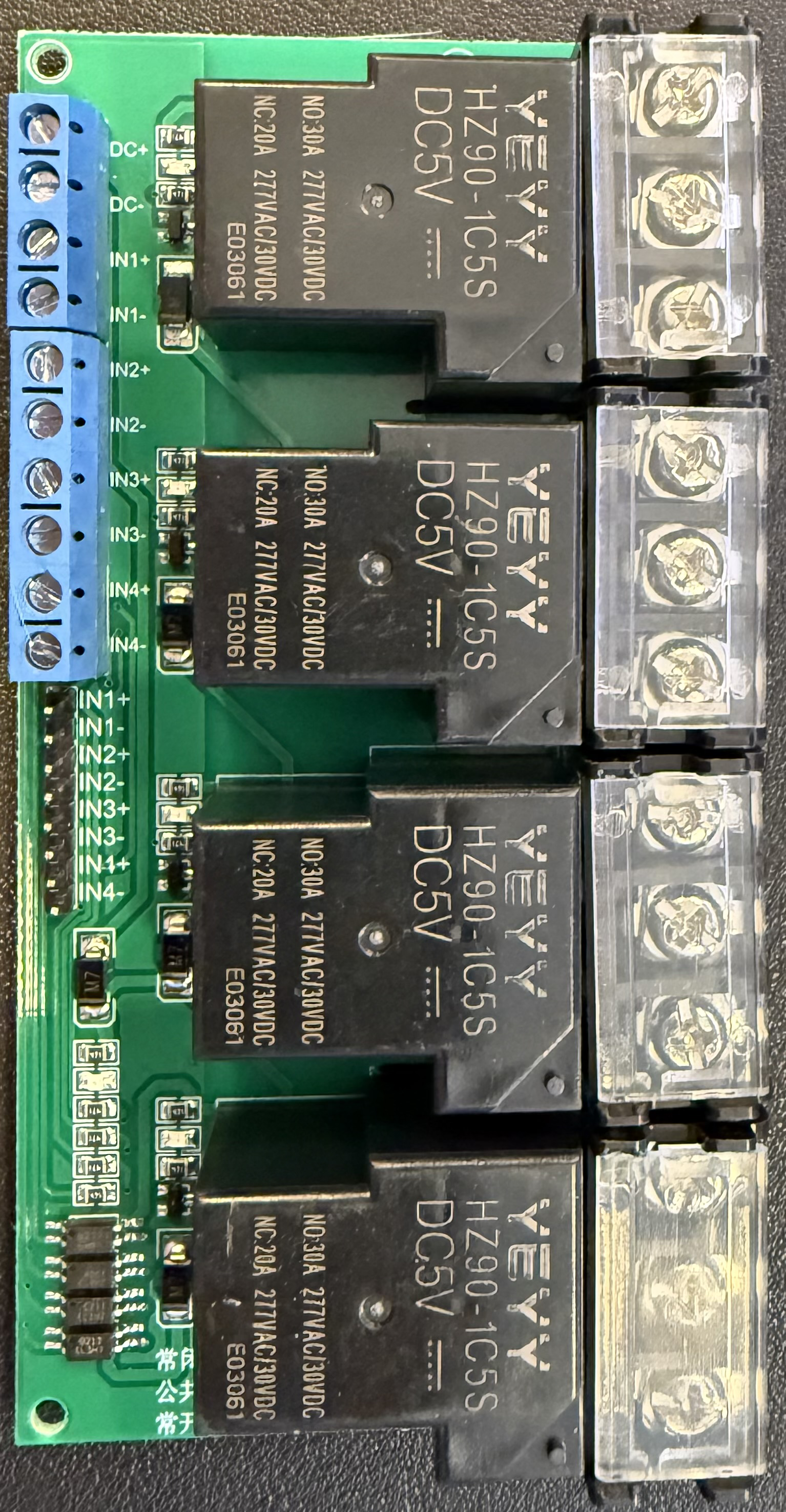
The 4 Channel 30A 5V Relay (YYG-4) is an electrically operated switch that allows a low-power signal to control a high-power circuit. This relay module can control up to 30 amps of current using a 5V signal and can switch four different circuits independently. It is commonly used in applications such as home automation, industrial automation, and various DIY projects.
Explore Projects Built with 4 Channel 30a 5V Relay
ESP32-Powered Wi-Fi Controlled Relay System
This circuit features an ESP32 microcontroller interfaced with two 4-channel 30A 5V relays. The ESP32 controls the relays through its GPIO pins, enabling it to switch high-power loads on and off.
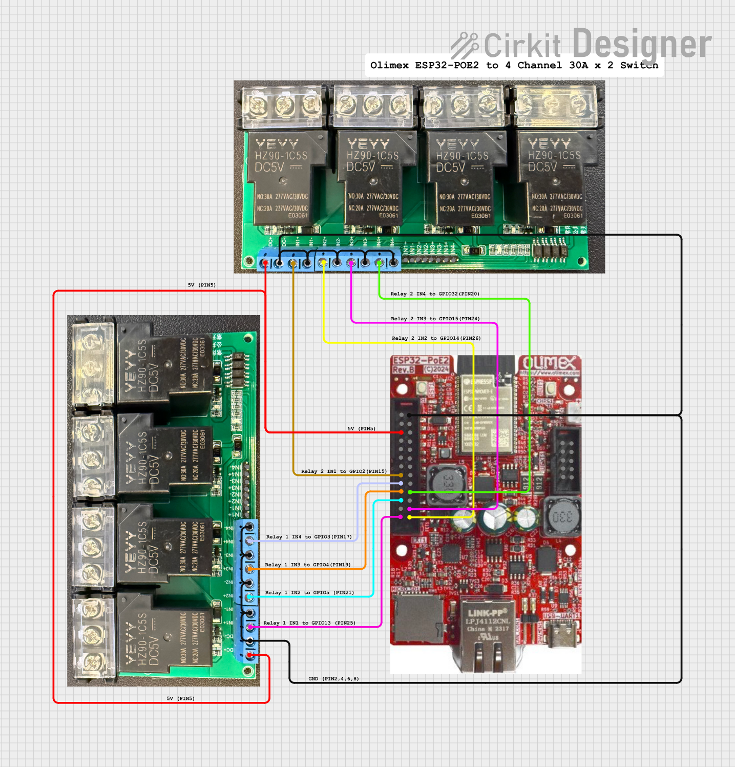
ESP32-POE-ISO Wi-Fi Controlled 4-Channel Relay Module

This circuit features an ESP32-POE-ISO microcontroller connected to a 4-channel 30A 5V relay module. The ESP32 controls the relay channels via its GPIO pins, allowing for the switching of high-power devices through the relay module.
Battery-Powered 4-Channel Relay Control with LED Indicators

This circuit consists of a 5V battery powering a 4-channel relay module, which controls four LEDs (red, yellow, green, and blue) through individual resistors. Each relay channel is activated by a corresponding SPST toggle switch, allowing manual control of the LEDs.
Wi-Fi Controlled Relay System with ESP32 and LED Indicators

This circuit is a control system using an ESP32 microcontroller to manage a 4-channel relay module, which in turn controls various loads. The relays are activated by rocker switches and provide visual feedback through LEDs, while power is supplied and regulated by an HLK-PM12 module and protected by a fuse and circuit breaker.
Explore Projects Built with 4 Channel 30a 5V Relay
ESP32-Powered Wi-Fi Controlled Relay System
This circuit features an ESP32 microcontroller interfaced with two 4-channel 30A 5V relays. The ESP32 controls the relays through its GPIO pins, enabling it to switch high-power loads on and off.
ESP32-POE-ISO Wi-Fi Controlled 4-Channel Relay Module
This circuit features an ESP32-POE-ISO microcontroller connected to a 4-channel 30A 5V relay module. The ESP32 controls the relay channels via its GPIO pins, allowing for the switching of high-power devices through the relay module.
Battery-Powered 4-Channel Relay Control with LED Indicators
This circuit consists of a 5V battery powering a 4-channel relay module, which controls four LEDs (red, yellow, green, and blue) through individual resistors. Each relay channel is activated by a corresponding SPST toggle switch, allowing manual control of the LEDs.
Wi-Fi Controlled Relay System with ESP32 and LED Indicators
This circuit is a control system using an ESP32 microcontroller to manage a 4-channel relay module, which in turn controls various loads. The relays are activated by rocker switches and provide visual feedback through LEDs, while power is supplied and regulated by an HLK-PM12 module and protected by a fuse and circuit breaker.
Common Applications and Use Cases
- Home automation systems
- Industrial control systems
- Motor control
- Lighting control
- DIY electronics projects
- Arduino and other microcontroller projects
Technical Specifications
Key Technical Details
| Parameter | Value |
|---|---|
| Operating Voltage | 5V DC |
| Trigger Voltage | 5V DC |
| Maximum Current | 30A |
| Number of Channels | 4 |
| Relay Type | SPDT (Single Pole Double Throw) |
| Dimensions | 138mm x 55mm x 18mm |
| Weight | 120g |
Pin Configuration and Descriptions
Input Pins
| Pin Number | Pin Name | Description |
|---|---|---|
| 1 | IN1 | Control signal for Relay 1 (Active Low) |
| 2 | IN2 | Control signal for Relay 2 (Active Low) |
| 3 | IN3 | Control signal for Relay 3 (Active Low) |
| 4 | IN4 | Control signal for Relay 4 (Active Low) |
| 5 | GND | Ground |
| 6 | VCC | 5V Power Supply |
Output Pins (for each relay channel)
| Pin Number | Pin Name | Description |
|---|---|---|
| 1 | COM | Common terminal |
| 2 | NO | Normally Open terminal |
| 3 | NC | Normally Closed terminal |
Usage Instructions
How to Use the Component in a Circuit
- Power Supply: Connect the VCC pin to a 5V power supply and the GND pin to the ground.
- Control Signals: Connect the IN1, IN2, IN3, and IN4 pins to the digital output pins of a microcontroller (e.g., Arduino).
- Load Connections: Connect the load to the COM, NO, and NC terminals of each relay channel as required by your application.
Important Considerations and Best Practices
- Ensure that the power supply voltage is stable and within the specified range (5V DC).
- Use appropriate heat sinks or cooling mechanisms if the relay is switching high currents frequently.
- Avoid switching inductive loads without proper flyback diodes to prevent voltage spikes.
- Ensure that the control signals are properly isolated from the high-power circuit to prevent damage to the microcontroller.
Example: Connecting to an Arduino UNO
Circuit Diagram
Arduino UNO          Relay Module
-----------          -------------
5V         --------> VCC
GND        --------> GND
D2         --------> IN1
D3         --------> IN2
D4         --------> IN3
D5         --------> IN4
Sample Code
// Define relay control pins
const int relay1 = 2;
const int relay2 = 3;
const int relay3 = 4;
const int relay4 = 5;

void setup() {
  // Initialize relay control pins as outputs
  pinMode(relay1, OUTPUT);
  pinMode(relay2, OUTPUT);
  pinMode(relay3, OUTPUT);
  pinMode(relay4, OUTPUT);

  // Set all relays to off state (HIGH)
  digitalWrite(relay1, HIGH);
  digitalWrite(relay2, HIGH);
  digitalWrite(relay3, HIGH);
  digitalWrite(relay4, HIGH);
}

void loop() {
  // Example: Turn on Relay 1 for 2 seconds, then turn it off
  digitalWrite(relay1, LOW); // Turn on Relay 1
  delay(2000);               // Wait for 2 seconds
  digitalWrite(relay1, HIGH);// Turn off Relay 1
  delay(2000);               // Wait for 2 seconds

  // Repeat for other relays as needed
}
Troubleshooting and FAQs
Common Issues Users Might Face
- Relay Not Switching: Ensure that the control signal voltage is correct and that the relay module is properly powered.
- High Current Load Not Working: Verify that the load current does not exceed the relay's maximum current rating (30A).
- Microcontroller Resetting: This could be due to voltage spikes from inductive loads. Use flyback diodes to protect the microcontroller.
Solutions and Tips for Troubleshooting
- Check Connections: Ensure all connections are secure and correct.
- Verify Power Supply: Make sure the power supply is stable and within the specified voltage range.
- Use Flyback Diodes: For inductive loads, use flyback diodes to prevent voltage spikes.
- Isolate Control Signals: Use optocouplers or other isolation techniques to protect the microcontroller from high-power circuits.
By following this documentation, users should be able to effectively utilize the 4 Channel 30A 5V Relay (YYG-4) in their projects, ensuring reliable and safe operation.