How to Use DHT11 Sensor Module: Examples, Pinouts, and Specs
Introduction
The DHT11 Sensor Module is a digital temperature and humidity sensor that provides accurate readings of environmental conditions. It features a single-wire digital interface, making it easy to integrate with microcontrollers such as Arduino, Raspberry Pi, and other development boards. The DHT11 is widely used in applications such as weather stations, HVAC systems, greenhouses, and other projects requiring environmental monitoring. Its compact size, low power consumption, and reliable performance make it a popular choice for both hobbyists and professionals.
Explore Projects Built with DHT11 Sensor Module
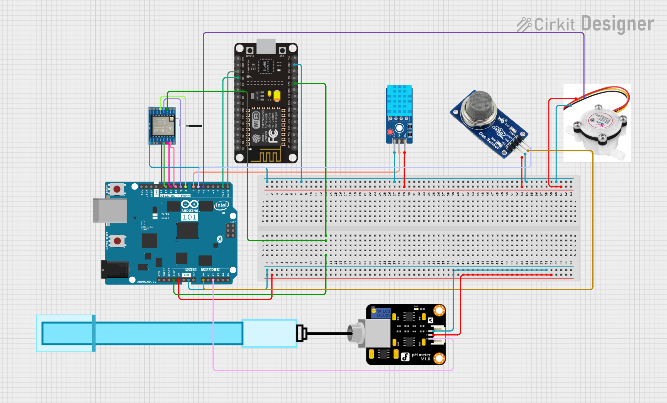
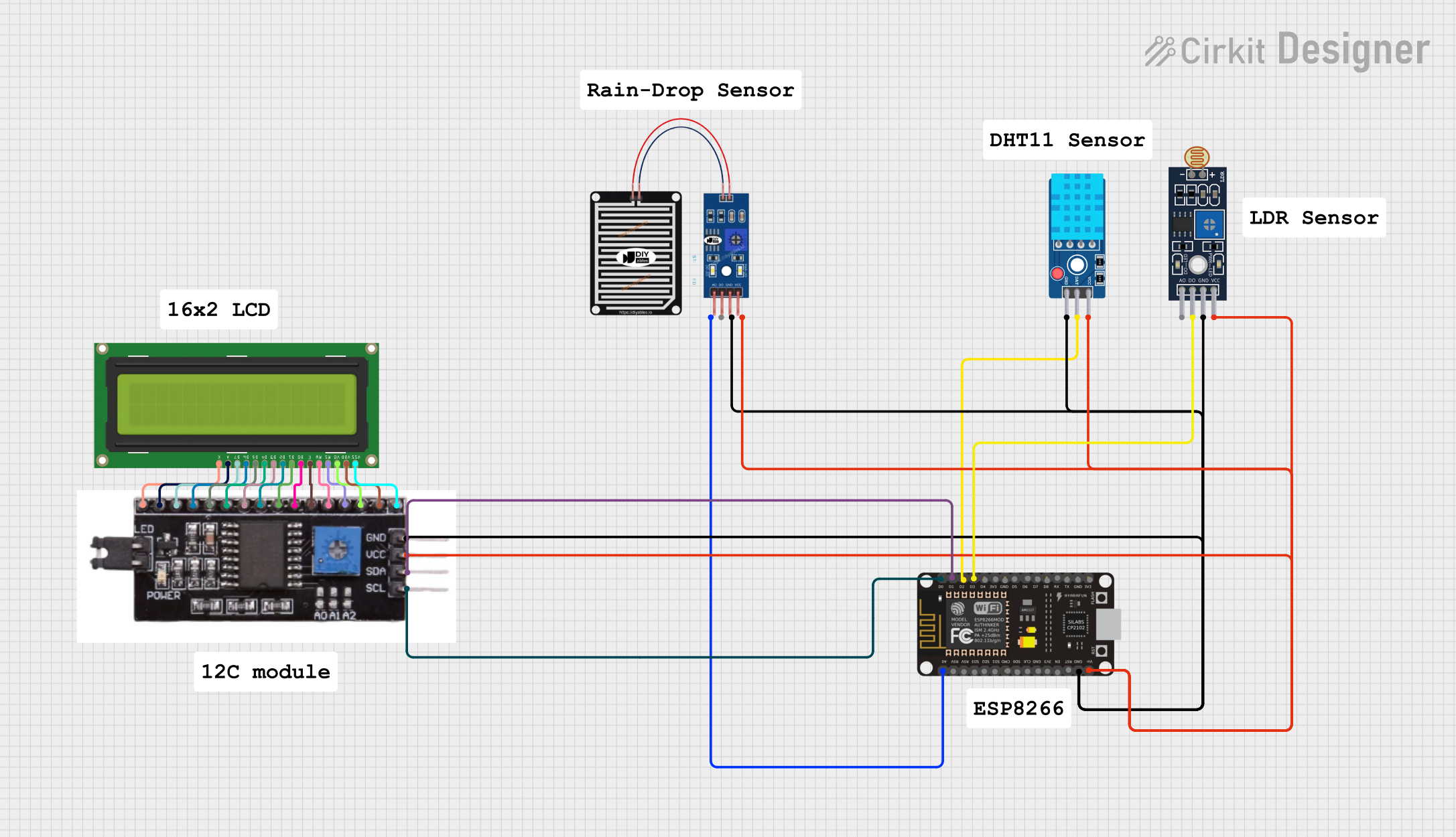
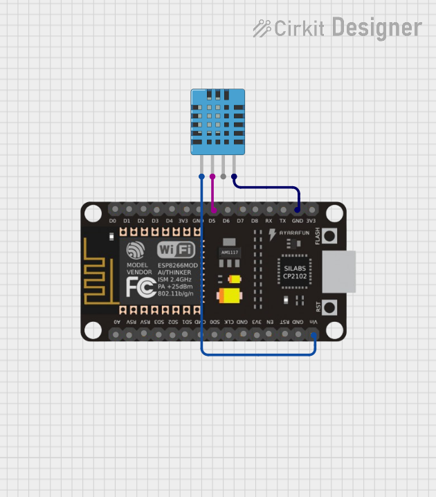

Explore Projects Built with DHT11 Sensor Module
Technical Specifications
The DHT11 Sensor Module has the following key technical specifications:
| Parameter | Value |
|---|---|
| Operating Voltage | 3.3V to 5.5V |
| Operating Current | 0.3mA (measuring), 60µA (standby) |
| Temperature Range | 0°C to 50°C |
| Temperature Accuracy | ±2°C |
| Humidity Range | 20% to 90% RH |
| Humidity Accuracy | ±5% RH |
| Sampling Period | 1 second |
| Communication Protocol | Single-wire digital interface |
| Dimensions | 15mm x 12mm x 5mm |
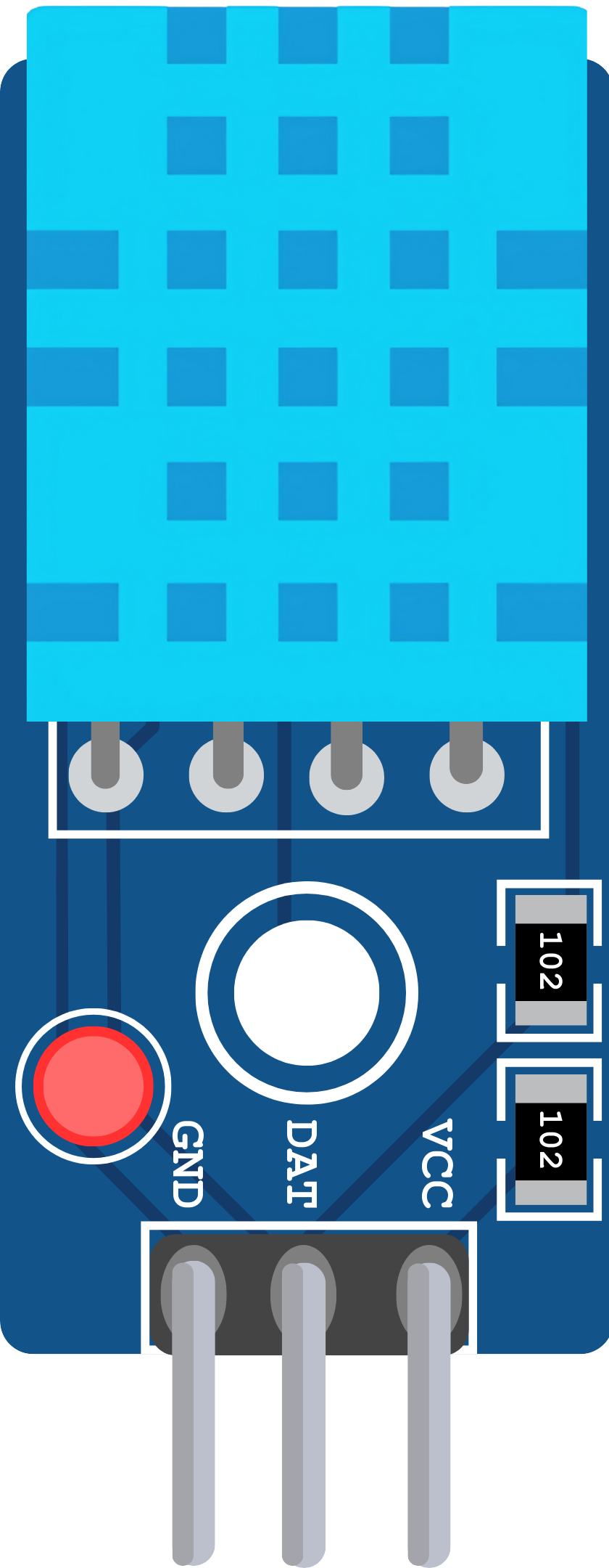
Pin Configuration and Descriptions
The DHT11 Sensor Module typically has three or four pins, depending on the module version. Below is the pin configuration for the most common 3-pin module:
| Pin | Name | Description |
|---|---|---|
| 1 | VCC | Power supply pin (3.3V to 5.5V) |
| 2 | DATA | Digital data output pin for temperature and humidity readings |
| 3 | GND | Ground pin |
For 4-pin modules, the additional pin is usually a "NC" (Not Connected) pin and can be ignored.
Usage Instructions
How to Use the DHT11 Sensor Module in a Circuit
Connect the Pins:
- Connect the
VCCpin to the 5V or 3.3V power supply of your microcontroller. - Connect the
GNDpin to the ground (GND) of your microcontroller. - Connect the
DATApin to a digital input pin on your microcontroller. Use a 10kΩ pull-up resistor between theDATApin andVCCto ensure stable communication.
- Connect the
Install Required Libraries:
- If using an Arduino, install the "DHT sensor library" by Adafruit from the Arduino Library Manager.
Write the Code:
- Use the following example code to read temperature and humidity data from the DHT11 sensor.
// Include the necessary libraries
#include <DHT.h>

// Define the pin where the DHT11 is connected
#define DHTPIN 2  // Connect DATA pin to digital pin 2

// Define the DHT type (DHT11 in this case)
#define DHTTYPE DHT11

// Initialize the DHT sensor
DHT dht(DHTPIN, DHTTYPE);

void setup() {
  Serial.begin(9600);  // Start the serial communication
  Serial.println("DHT11 Sensor Module Test");
  dht.begin();  // Initialize the DHT sensor
}

void loop() {
  delay(2000);  // Wait 2 seconds between readings

  // Read temperature and humidity
  float humidity = dht.readHumidity();
  float temperature = dht.readTemperature();

  // Check if the readings are valid
  if (isnan(humidity) || isnan(temperature)) {
    Serial.println("Failed to read from DHT sensor!");
    return;
  }

  // Print the results to the Serial Monitor
  Serial.print("Humidity: ");
  Serial.print(humidity);
  Serial.print(" %\t");
  Serial.print("Temperature: ");
  Serial.print(temperature);
  Serial.println(" °C");
}
Important Considerations and Best Practices
- Sampling Rate: The DHT11 has a sampling period of 1 second. Avoid reading data more frequently than once per second to ensure accurate results.
- Pull-Up Resistor: Always use a 10kΩ pull-up resistor on the
DATApin to stabilize the signal. - Environmental Conditions: The DHT11 is designed for indoor use. Avoid exposing it to extreme temperatures or humidity levels outside its specified range.
- Cable Length: Keep the cable length between the sensor and the microcontroller as short as possible to prevent signal degradation.
Troubleshooting and FAQs
Common Issues and Solutions
No Data or Incorrect Readings:
- Ensure the
DATApin is connected to the correct digital pin on the microcontroller. - Verify that the pull-up resistor is properly connected between the
DATApin andVCC. - Check the power supply voltage (3.3V to 5.5V) to ensure it is within the operating range.
- Ensure the
"Failed to Read from DHT Sensor" Error:
- This error occurs when the sensor does not respond. Double-check the wiring and ensure the sensor is powered.
- Ensure the DHT sensor library is correctly installed and the
DHTTYPEis set toDHT11.
Inconsistent or Fluctuating Readings:
- Ensure the sensor is not exposed to rapid temperature or humidity changes.
- Verify that the pull-up resistor is of the correct value (10kΩ).
FAQs
Q: Can the DHT11 measure negative temperatures?
A: No, the DHT11 can only measure temperatures in the range of 0°C to 50°C. For applications requiring negative temperature measurements, consider using the DHT22 sensor.
Q: Can I use the DHT11 outdoors?
A: The DHT11 is not designed for outdoor use. Prolonged exposure to extreme environmental conditions may damage the sensor or reduce its accuracy.
Q: What is the maximum cable length for the DHT11?
A: The maximum recommended cable length is approximately 20 meters. However, longer cables may require a lower pull-up resistor value (e.g., 4.7kΩ) to maintain signal integrity.
Q: How do I know if my DHT11 is faulty?
A: If the sensor consistently fails to provide readings despite correct wiring and code, it may be damaged. Replace the sensor and test again.
This concludes the documentation for the DHT11 Sensor Module.