Cirkit Designer Logo
Cirkit Designer
Your all-in-one circuit design IDE
Home / 
Component Documentation

How to Use 8 Bits 5V WS2812 5050 RGB : Examples, Pinouts, and Specs

Image of 8 Bits 5V WS2812 5050 RGB
Cirkit Designer LogoDesign with 8 Bits 5V WS2812 5050 RGB in Cirkit Designer

Introduction

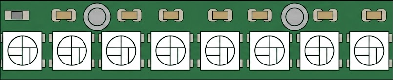
The 8 Bits 5V WS2812 5050 RGB is a programmable RGB LED strip that operates at 5V. It features individually addressable 5050 RGB LEDs, allowing for vibrant color displays and dynamic lighting effects. Each LED contains an integrated driver chip, enabling precise control of brightness and color through a single data line. This component is widely used in decorative lighting, displays, and DIY electronics projects.

Explore Projects Built with 8 Bits 5V WS2812 5050 RGB

Use Cirkit Designer to design, explore, and prototype these projects online. Some projects support real-time simulation. Click "Open Project" to start designing instantly!
Arduino Mega 2560 and Raspberry Pi 4B Controlled WS2812 RGB LED Strip
Image of circuit_image: A project utilizing 8 Bits 5V WS2812 5050 RGB  in a practical application
This circuit features an Arduino Mega 2560 microcontroller programmed to control a WS2812 RGB LED strip and a white LED, indicating status or providing user feedback. The Arduino and the LED strip are powered by a common 5V supply, and the circuit includes interfacing with a Raspberry Pi 4B for potential communication or coordination between the two boards.
Cirkit Designer LogoOpen Project in Cirkit Designer
Arduino UNO Controlled WS2812 RGB LED Strip with Custom Color Patterns
Image of LED: A project utilizing 8 Bits 5V WS2812 5050 RGB  in a practical application
This circuit consists of an Arduino UNO microcontroller connected to a WS2812 RGB LED strip. The Arduino controls the LED strip by sending data signals through pin D8, while the 5V and GND pins provide power. The provided code initializes the LED strip and sets specific colors to the first three LEDs.
Cirkit Designer LogoOpen Project in Cirkit Designer
Arduino UNO Controlled RGB LED Matrix with Bluetooth Connectivity and Audio Output
Image of the bell : A project utilizing 8 Bits 5V WS2812 5050 RGB  in a practical application
This is an interactive display and communication circuit. It uses an Arduino UNO to drive multiple WS2812 RGB LED matrices for visual output, interfaces with a DS3231 RTC for time-related functions, and communicates wirelessly via an HC-05 Bluetooth module. Additionally, it features audio output capabilities through a speaker connected to a PAM8403 audio amplifier.
Cirkit Designer LogoOpen Project in Cirkit Designer
ESP32-Controlled WS2812 RGB LED Strip Lighting System
Image of Test: A project utilizing 8 Bits 5V WS2812 5050 RGB  in a practical application
This circuit is designed to control a WS2812 RGB LED strip using an ESP32 microcontroller. The 5V DC power supply provides power to both the ESP32 and the LED strip. The ESP32's digital pin (D13) is connected to the LED strip's data input (DIN) to enable programmable control of the LED colors and patterns.
Cirkit Designer LogoOpen Project in Cirkit Designer

Explore Projects Built with 8 Bits 5V WS2812 5050 RGB

Use Cirkit Designer to design, explore, and prototype these projects online. Some projects support real-time simulation. Click "Open Project" to start designing instantly!
Image of circuit_image: A project utilizing 8 Bits 5V WS2812 5050 RGB  in a practical application
Arduino Mega 2560 and Raspberry Pi 4B Controlled WS2812 RGB LED Strip
This circuit features an Arduino Mega 2560 microcontroller programmed to control a WS2812 RGB LED strip and a white LED, indicating status or providing user feedback. The Arduino and the LED strip are powered by a common 5V supply, and the circuit includes interfacing with a Raspberry Pi 4B for potential communication or coordination between the two boards.
Cirkit Designer LogoOpen Project in Cirkit Designer
Image of LED: A project utilizing 8 Bits 5V WS2812 5050 RGB  in a practical application
Arduino UNO Controlled WS2812 RGB LED Strip with Custom Color Patterns
This circuit consists of an Arduino UNO microcontroller connected to a WS2812 RGB LED strip. The Arduino controls the LED strip by sending data signals through pin D8, while the 5V and GND pins provide power. The provided code initializes the LED strip and sets specific colors to the first three LEDs.
Cirkit Designer LogoOpen Project in Cirkit Designer
Image of the bell : A project utilizing 8 Bits 5V WS2812 5050 RGB  in a practical application
Arduino UNO Controlled RGB LED Matrix with Bluetooth Connectivity and Audio Output
This is an interactive display and communication circuit. It uses an Arduino UNO to drive multiple WS2812 RGB LED matrices for visual output, interfaces with a DS3231 RTC for time-related functions, and communicates wirelessly via an HC-05 Bluetooth module. Additionally, it features audio output capabilities through a speaker connected to a PAM8403 audio amplifier.
Cirkit Designer LogoOpen Project in Cirkit Designer
Image of Test: A project utilizing 8 Bits 5V WS2812 5050 RGB  in a practical application
ESP32-Controlled WS2812 RGB LED Strip Lighting System
This circuit is designed to control a WS2812 RGB LED strip using an ESP32 microcontroller. The 5V DC power supply provides power to both the ESP32 and the LED strip. The ESP32's digital pin (D13) is connected to the LED strip's data input (DIN) to enable programmable control of the LED colors and patterns.
Cirkit Designer LogoOpen Project in Cirkit Designer

Common Applications

  • Decorative lighting for homes, events, and holidays
  • LED displays and signage
  • Wearable electronics
  • Gaming setups and PC case lighting
  • DIY projects with microcontrollers like Arduino or Raspberry Pi

Technical Specifications

The WS2812 5050 RGB LED strip is designed for ease of use and high performance. Below are its key technical details:

Key Specifications

Parameter Value
Operating Voltage 5V DC
LED Type 5050 RGB
Communication Protocol Single-wire (WS2812 protocol)
Number of LEDs 8 LEDs
Power Consumption ~60mA per LED (at full white)
Color Depth 24-bit (8 bits per channel)
Refresh Rate ~400 Hz
Operating Temperature -25°C to 80°C

Pin Configuration

The WS2812 LED strip has three main pins for operation:

Pin Name Description
VCC Power supply (5V DC)
GND Ground
DIN Data input for control signals

Note: Some strips may have an additional DOUT pin at the end of the strip for cascading multiple strips.

Usage Instructions

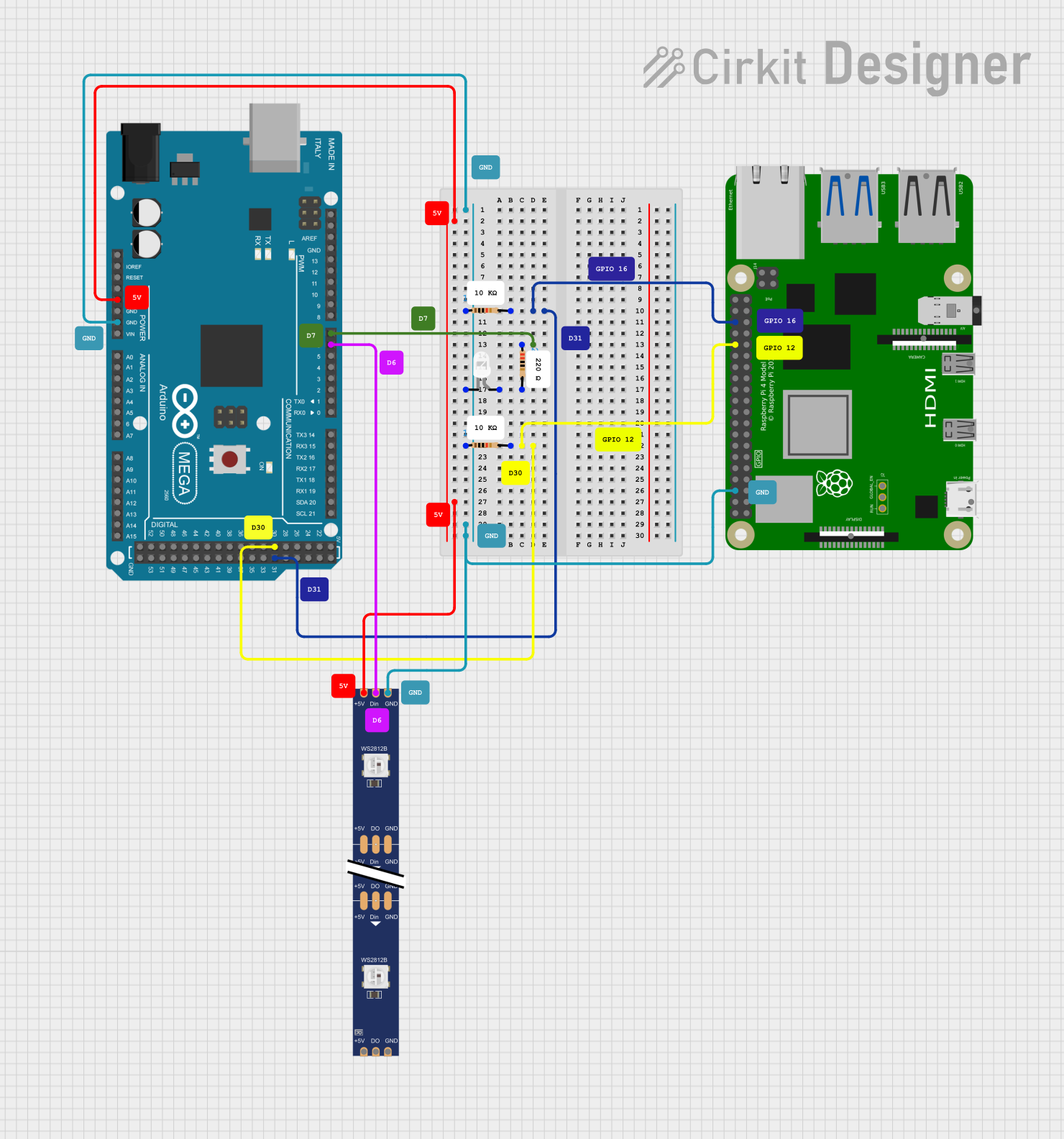
Connecting the WS2812 to a Circuit

  1. Power Supply: Connect the VCC pin to a 5V DC power source and the GND pin to ground.
  2. Data Line: Connect the DIN pin to the data output pin of your microcontroller (e.g., Arduino).
  3. Capacitor: Place a 1000 µF capacitor across VCC and GND to stabilize the power supply.
  4. Resistor: Use a 330-500 ohm resistor between the microcontroller's data pin and the DIN pin to protect the LEDs from voltage spikes.
  5. Cascading: To connect multiple strips, link the DOUT pin of the first strip to the DIN pin of the next strip.

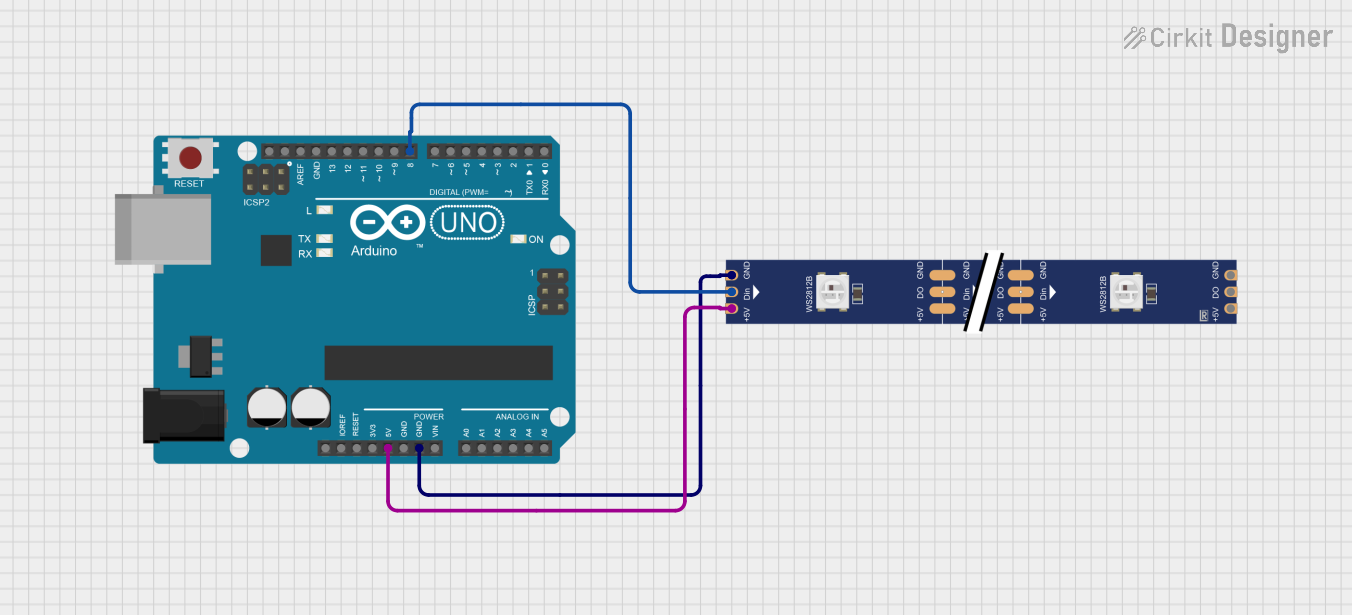
Arduino Example Code

Below is an example of how to control the WS2812 LED strip using an Arduino UNO and the Adafruit NeoPixel library:

#include <Adafruit_NeoPixel.h>

// Define the number of LEDs in the strip
#define NUM_LEDS 8

// Define the pin connected to the DIN pin of the WS2812 strip
#define DATA_PIN 6

// Create a NeoPixel object
Adafruit_NeoPixel strip = Adafruit_NeoPixel(NUM_LEDS, DATA_PIN, NEO_GRB + NEO_KHZ800);

void setup() {
  strip.begin();  // Initialize the NeoPixel library
  strip.show();   // Turn off all LEDs initially
}

void loop() {
  // Example: Cycle through colors
  for (int i = 0; i < strip.numPixels(); i++) {
    strip.setPixelColor(i, strip.Color(255, 0, 0)); // Set LED to red
    strip.show();                                   // Update the strip
    delay(100);                                     // Wait 100ms
  }
}

Best Practices

  • Power Supply: Ensure the power supply can handle the total current draw of the LEDs. For example, 8 LEDs at full brightness (white) will draw approximately 480mA.
  • Signal Integrity: Keep the data line as short as possible to avoid signal degradation. For longer distances, consider using a level shifter to boost the signal.
  • Heat Management: Avoid running the LEDs at full brightness for extended periods to prevent overheating.

Troubleshooting and FAQs

Common Issues

  1. LEDs not lighting up:

    • Check the power supply voltage (should be 5V).
    • Verify the connections to VCC, GND, and DIN.
    • Ensure the data pin on the microcontroller matches the pin defined in the code.
  2. Incorrect colors or flickering:

    • Verify the resistor on the data line (330-500 ohms recommended).
    • Check for loose or poor connections.
    • Ensure the correct color order (e.g., NEO_GRB in the code).
  3. Only the first LED works:

    • Check the data signal integrity.
    • Ensure the DIN pin of the second LED is properly connected to the DOUT pin of the first LED.

FAQs

Q: Can I cut the LED strip to a smaller size?
A: Yes, the strip can be cut at designated points (usually marked with a scissor icon). Ensure you reconnect the DIN, VCC, and GND pins properly.

Q: How many LEDs can I control with one microcontroller?
A: Theoretically, you can control hundreds of LEDs, but the refresh rate and memory usage of your microcontroller will limit performance.

Q: Can I power the strip directly from the Arduino?
A: No, the Arduino's 5V pin cannot supply enough current for multiple LEDs. Use an external 5V power supply.

By following this documentation, you can effectively integrate and troubleshoot the 8 Bits 5V WS2812 5050 RGB LED strip in your projects!