The STM32F446RE NUCLEO BOARD is a development board featuring the STM32F446RE microcontroller, which is based on the ARM Cortex-M4 core. This board is designed to provide a flexible platform for prototyping and developing embedded applications. It offers a wide range of peripherals, connectivity options, and compatibility with Arduino and ST morpho headers, making it suitable for both beginners and experienced developers.
Explore Projects Built with STM32F446RE NUCLEO BOARD
Use Cirkit Designer to design, explore, and prototype these projects online. Some projects support real-time simulation. Click "Open Project" to start designing instantly!
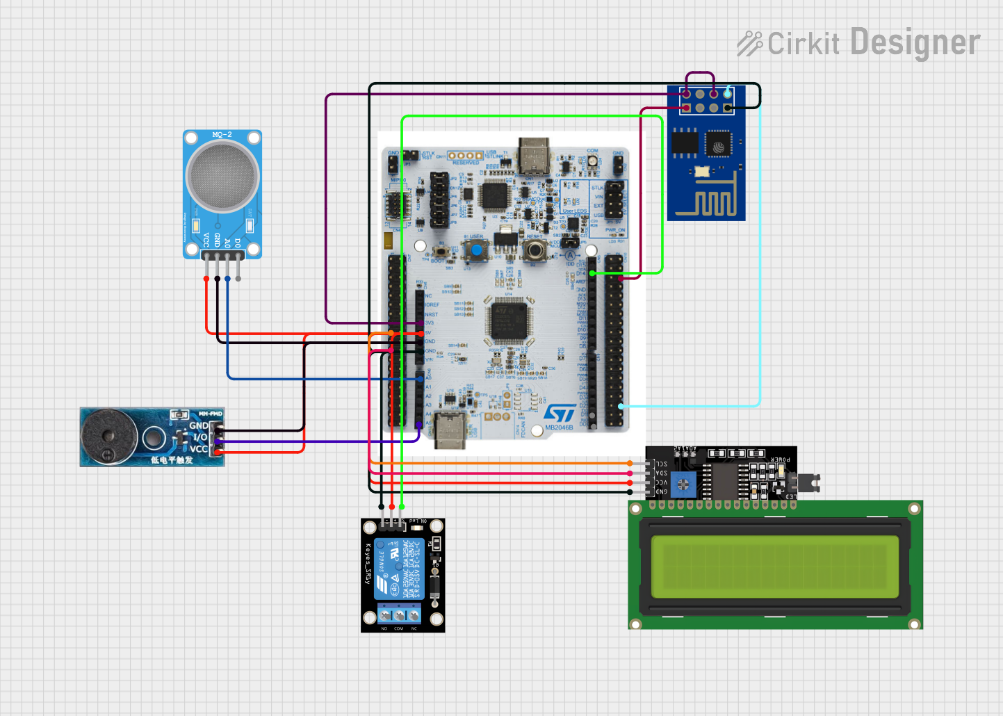
This circuit features a NUCLEO-F303RE microcontroller board interfaced with several modules for sensing, actuation, and communication. It uses I2C communication to display data on an LCD screen, UART communication to interface with an ESP8266 WiFi module, and reads an MQ-2 gas sensor via an ADC pin. The microcontroller also controls a buzzer for audible alerts and a relay module for switching higher power loads, possibly in response to sensor readings or remote commands received over WiFi.
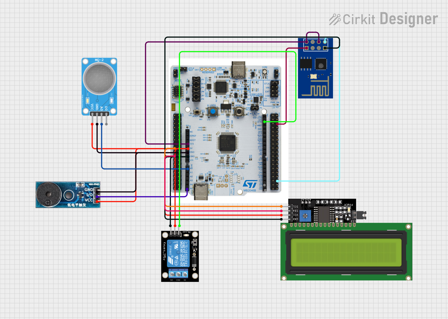
This circuit features a NUCLEO-F303RE microcontroller board interfaced with various modules for sensing, actuation, and communication. It includes an MQ-2 gas sensor for detecting combustible gases, a buzzer for audible alerts, and a relay for controlling high-power devices. Additionally, the circuit uses an ESP8266 WiFi module for wireless connectivity and an I2C LCD display for user interface and data display.
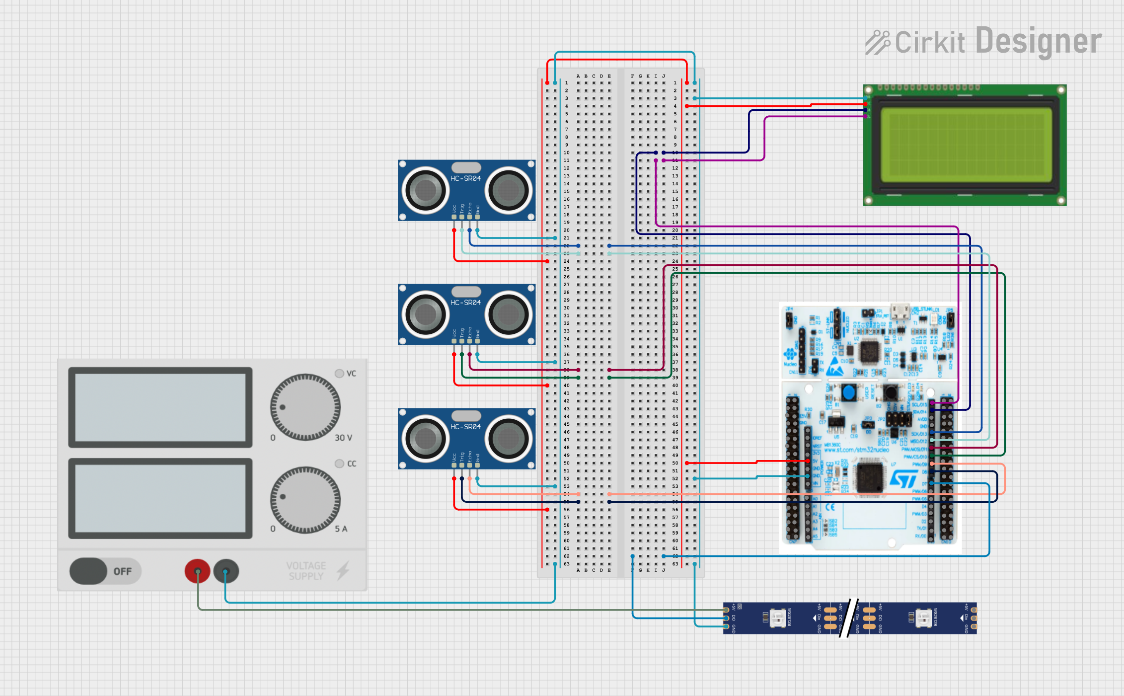
This circuit features a STM32 Nucleo F303RE microcontroller interfaced with three HC-SR04 ultrasonic sensors for distance measurement and a 20x4 LCD display over I2C for data output. Additionally, there is a WS2812 RGB LED strip controlled by the microcontroller for visual feedback. The power supply provides a common 5V to the LCD, ultrasonic sensors, LED strip, and the microcontroller's +5V input, with all components sharing a common ground.
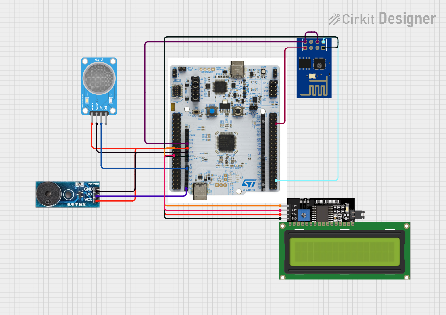
This circuit features a NUCLEO-F303RE microcontroller board interfaced with an ESP8266 ESP-01 WiFi module for wireless connectivity, an MQ-2 gas sensor for detecting combustible gases, a buzzer module for audible alerts, and an LCD display for visual feedback. The microcontroller communicates with the LCD via I2C and with the WiFi module via UART. The buzzer is driven by one of the microcontroller's timers, and the gas sensor's analog output is connected to an ADC pin on the microcontroller for gas concentration measurement.
Connectivity: Arduino Uno R3 compatibility and ST morpho headers
Pin Configuration and Descriptions
The STM32F446RE NUCLEO BOARD features multiple pin headers. Below is a summary of the key pin configurations:
Arduino-Compatible Header
Pin Name
Functionality
Description
A0-A5
Analog Input
6 analog input pins (12-bit ADC)
D0-D13
Digital I/O
14 digital I/O pins
PWM
Pulse Width Modulation
Available on specific digital pins
VIN
Power Input
External power supply (7-12V)
5V
Power Output
5V regulated output
3.3V
Power Output
3.3V regulated output
GND
Ground
Common ground
RESET
Reset
Resets the microcontroller
ST Morpho Header
Pin Name
Functionality
Description
PAx, PBx
GPIO Pins
General-purpose I/O pins
VDD
Power Supply
3.3V power supply
GND
Ground
Common ground
NRST
Reset
Microcontroller reset
OSC_IN
External Clock Input
Input for external oscillator
OSC_OUT
External Clock Output
Output for external oscillator
Usage Instructions
How to Use the Component in a Circuit
Powering the Board:
Connect the board to your computer via a micro-USB cable for power and programming.
Alternatively, use the VIN pin to supply 7-12V or the 5V pin for regulated power.
Programming the Board:
Use the onboard ST-LINK/V2-1 debugger/programmer to upload code.
Compatible with STM32CubeIDE, Keil, IAR, and Arduino IDE.
Connecting Peripherals:
Use the Arduino-compatible headers for shields and external modules.
Use the ST morpho headers for advanced GPIO and peripheral access.
Running the Code:
After uploading the code, the board will automatically reset and execute the program.
Important Considerations and Best Practices
Ensure the input voltage does not exceed the specified range to avoid damage.
Use decoupling capacitors when connecting external components to reduce noise.
Avoid connecting high-current loads directly to GPIO pins; use transistors or relays.
For real-time applications, configure the clock settings carefully to achieve the desired performance.
Example Code for Arduino IDE
Below is an example code to blink an LED connected to pin D13:
// Blink an LED on pin D13 of the STM32F446RE NUCLEO BOARD
void setup() {
  pinMode(13, OUTPUT); // Set pin D13 as an output
}

void loop() {
  digitalWrite(13, HIGH); // Turn the LED on
  delay(1000);            // Wait for 1 second
  digitalWrite(13, LOW);  // Turn the LED off
  delay(1000);            // Wait for 1 second
}
Troubleshooting and FAQs
Common Issues and Solutions
Board Not Detected by Computer:
Ensure the USB cable is functional and supports data transfer.
Check if the ST-LINK driver is installed on your computer.
Code Upload Fails:
Verify that the correct board and port are selected in the IDE.
Ensure no other application is using the ST-LINK interface.
Peripherals Not Working:
Double-check the wiring and connections.
Confirm that the correct pins are configured in the code.
Board Overheating:
Ensure the input voltage is within the specified range.
Avoid drawing excessive current from the GPIO pins.
FAQs
Q: Can I use the STM32F446RE NUCLEO BOARD with Arduino libraries?
A: Yes, the board is compatible with the Arduino IDE and supports many Arduino libraries.
Q: How do I reset the board?
A: Press the RESET button on the board or use the NRST pin.
Q: Can I use an external debugger with this board?
A: Yes, the board supports external debuggers via the SWD interface.
Q: What is the maximum clock speed of the STM32F446RE?
A: The microcontroller can operate at a maximum clock speed of 180 MHz.


 Open Project in Cirkit Designer