How to Use 4 Channel SSR w/ Grove I2C: Examples, Pinouts, and Specs
Introduction
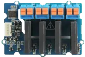
The 4 Channel SSR w/ Grove I2C (Manufacturer Part ID: 103020135) by Seeed Studio is a versatile Solid State Relay (SSR) module designed for controlling high-power devices using low-power signals. This module features four independent SSR channels, allowing users to control multiple devices simultaneously. Its Grove I2C interface ensures seamless integration with microcontrollers and development boards, such as Arduino and Raspberry Pi, making it ideal for IoT, home automation, and industrial control applications.
Explore Projects Built with 4 Channel SSR w/ Grove I2C
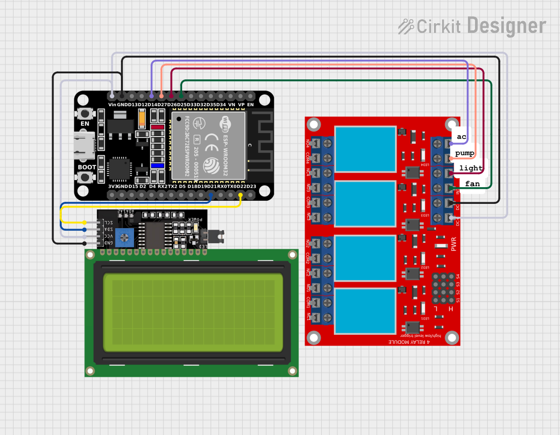

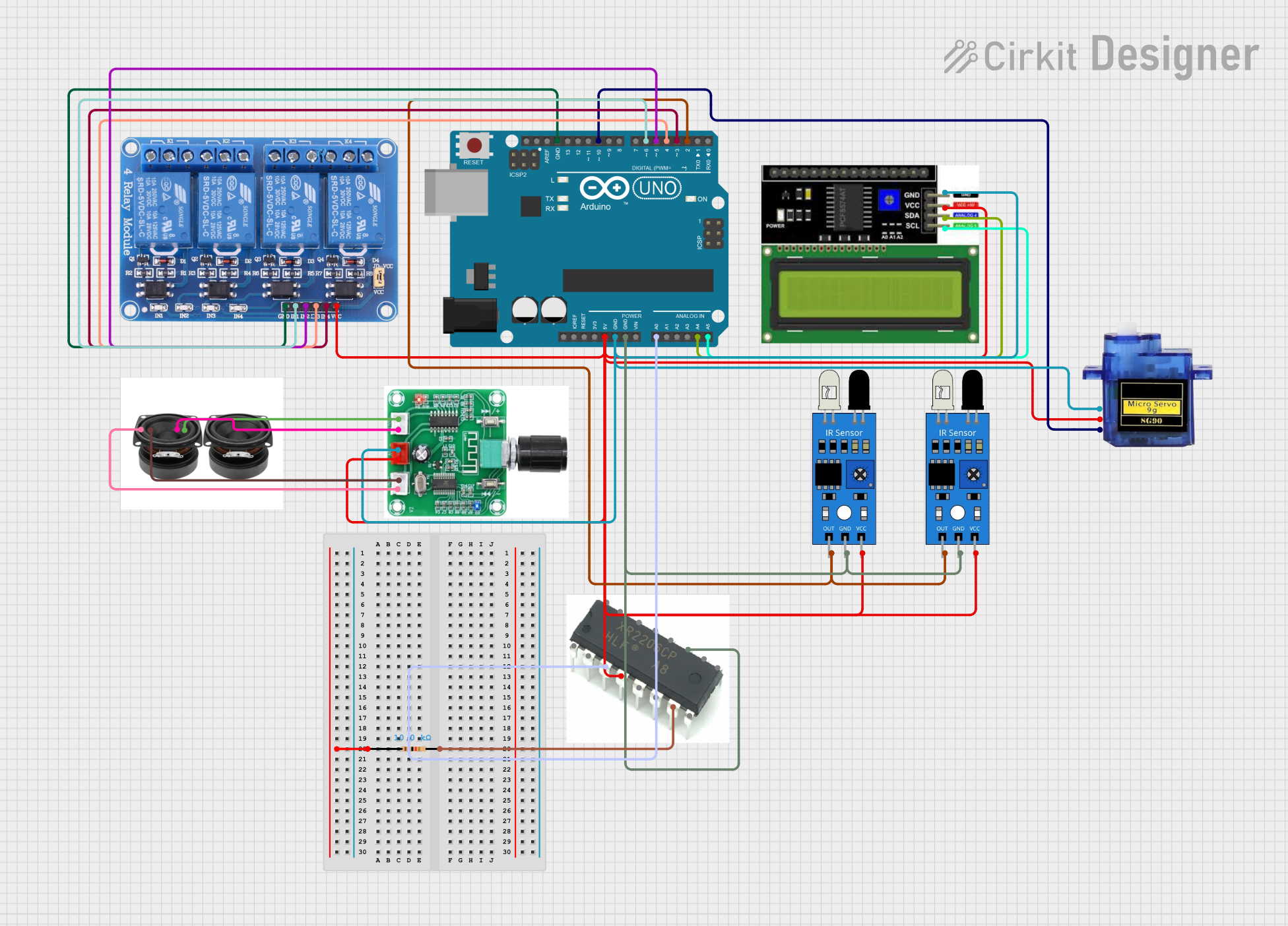

Explore Projects Built with 4 Channel SSR w/ Grove I2C
Common Applications
- Home automation (e.g., controlling lights, fans, or appliances)
- Industrial equipment control
- IoT projects requiring high-power device management
- Robotics and motor control
- Smart agriculture systems
Technical Specifications
Key Technical Details
| Parameter | Value |
|---|---|
| Operating Voltage | 5V DC |
| Control Interface | Grove I2C |
| Communication Protocol | I2C |
| Relay Type | Solid State Relay (SSR) |
| Number of Channels | 4 |
| Maximum Load Voltage | 240V AC |
| Maximum Load Current | 2A per channel |
| Isolation Voltage | 2500V RMS |
| Dimensions | 40mm x 60mm |
| Operating Temperature | -40°C to 85°C |
Pin Configuration and Descriptions
The module features a Grove I2C connector and four output terminals for connecting external devices. Below is the pin configuration:
Grove I2C Connector
| Pin Name | Description |
|---|---|
| VCC | 5V power supply input |
| GND | Ground |
| SDA | I2C data line |
| SCL | I2C clock line |
Output Terminals
| Terminal Name | Description |
|---|---|
| CH1+ / CH1- | Positive and negative terminals for Channel 1 |
| CH2+ / CH2- | Positive and negative terminals for Channel 2 |
| CH3+ / CH3- | Positive and negative terminals for Channel 3 |
| CH4+ / CH4- | Positive and negative terminals for Channel 4 |
Usage Instructions
How to Use the Component in a Circuit
- Power the Module: Connect the Grove I2C connector to a 5V power source, such as an Arduino UNO or a Grove Base Shield.
- Connect the Load: Attach the high-power devices (e.g., lights, motors) to the output terminals (CH1+/- to CH4+/-). Ensure the load does not exceed 240V AC or 2A per channel.
- I2C Communication: Connect the SDA and SCL pins of the Grove I2C connector to the corresponding pins on your microcontroller.
- Control the Relays: Use I2C commands to control the state of each relay channel (ON/OFF).
Important Considerations and Best Practices
- Load Ratings: Ensure the connected load does not exceed the maximum voltage (240V AC) or current (2A per channel).
- Isolation: The SSR provides electrical isolation between the control and load sides. However, proper grounding and safety precautions should still be followed.
- Heat Dissipation: For continuous operation at high loads, ensure adequate ventilation or cooling to prevent overheating.
- I2C Address: The default I2C address of the module is
0x11. If multiple I2C devices are used, ensure there are no address conflicts.
Example Code for Arduino UNO
Below is an example Arduino sketch to control the 4 Channel SSR module using I2C:
#include <Wire.h> // Include the Wire library for I2C communication

#define SSR_I2C_ADDRESS 0x11 // Default I2C address of the SSR module

void setup() {
  Wire.begin(); // Initialize I2C communication
  Serial.begin(9600); // Initialize serial communication for debugging
  Serial.println("4 Channel SSR w/ Grove I2C Example");
}

void loop() {
  // Turn ON Channel 1
  controlRelay(1, true);
  delay(2000); // Wait for 2 seconds

  // Turn OFF Channel 1
  controlRelay(1, false);
  delay(2000); // Wait for 2 seconds
}

// Function to control a specific relay channel
void controlRelay(uint8_t channel, bool state) {
  Wire.beginTransmission(SSR_I2C_ADDRESS); // Start I2C communication
  Wire.write(channel); // Specify the relay channel (1 to 4)
  Wire.write(state ? 1 : 0); // Write 1 to turn ON, 0 to turn OFF
  Wire.endTransmission(); // End I2C communication

  // Debug message
  Serial.print("Channel ");
  Serial.print(channel);
  Serial.println(state ? " ON" : " OFF");
}
Notes:
- Replace
SSR_I2C_ADDRESSwith the correct I2C address if it has been changed. - Ensure the Grove I2C cable is securely connected to avoid communication issues.
Troubleshooting and FAQs
Common Issues and Solutions
Relays Not Responding
- Cause: Incorrect I2C address or wiring.
- Solution: Verify the I2C address and ensure SDA/SCL pins are correctly connected.
Load Not Turning ON/OFF
- Cause: Load exceeds the maximum voltage or current rating.
- Solution: Check the load specifications and ensure they are within the module's limits.
Overheating
- Cause: Continuous operation at high loads without proper cooling.
- Solution: Provide adequate ventilation or use a heat sink.
I2C Communication Errors
- Cause: Address conflict or loose connections.
- Solution: Check for address conflicts and ensure all connections are secure.
FAQs
Q: Can this module control DC loads?
A: No, this module is designed for AC loads only. For DC loads, use a DC-compatible relay module.Q: How do I change the I2C address?
A: Refer to the manufacturer's documentation for instructions on changing the I2C address.Q: Can I use this module with a Raspberry Pi?
A: Yes, the Grove I2C interface is compatible with Raspberry Pi. Use the appropriate I2C libraries for Python.Q: Is the module safe for high-power applications?
A: Yes, the SSR provides electrical isolation and is rated for up to 240V AC and 2A per channel. However, always follow safety guidelines when working with high voltages.