How to Use INDUSBOARD V2 : Examples, Pinouts, and Specs
INDUSBOARD V2 Documentation
1. Introduction
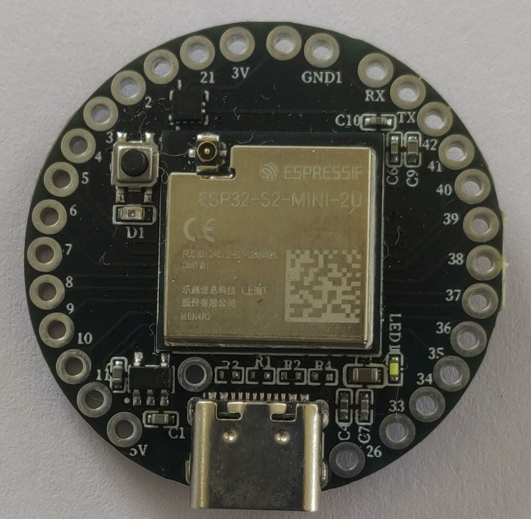
The INDUSBOARD V2 is a versatile development board designed specifically for industrial applications. It features multiple I/O options, communication interfaces, and robust power management, making it an ideal choice for creating and testing industrial automation projects. Whether you are a hobbyist or a professional engineer, the INDUSBOARD V2 provides the flexibility and reliability needed for a wide range of industrial applications.
Common Applications and Use Cases
- Industrial automation and control systems
- Data acquisition and monitoring
- Prototyping and testing of industrial equipment
- Remote sensing and telemetry
- Process control and instrumentation
2. Technical Specifications
Key Technical Details
| Parameter | Value |
|---|---|
| Operating Voltage | 5V / 12V |
| Input Voltage Range | 7V - 24V |
| Digital I/O Pins | 14 (6 PWM outputs) |
| Analog Input Pins | 6 |
| Communication Interfaces | UART, I2C, SPI, CAN |
| Power Management | Onboard voltage regulators |
| Dimensions | 100mm x 80mm |
| Operating Temperature | -40°C to 85°C |
Pin Configuration and Descriptions
| Pin Number | Pin Name | Description |
|---|---|---|
| 1 | GND | Ground |
| 2 | VCC | Power Supply (5V/12V) |
| 3 | D0 | Digital I/O Pin 0 |
| 4 | D1 | Digital I/O Pin 1 |
| 5 | D2 | Digital I/O Pin 2 |
| 6 | D3 | Digital I/O Pin 3 (PWM) |
| 7 | D4 | Digital I/O Pin 4 |
| 8 | D5 | Digital I/O Pin 5 (PWM) |
| 9 | D6 | Digital I/O Pin 6 (PWM) |
| 10 | D7 | Digital I/O Pin 7 |
| 11 | D8 | Digital I/O Pin 8 |
| 12 | D9 | Digital I/O Pin 9 (PWM) |
| 13 | D10 | Digital I/O Pin 10 (PWM) |
| 14 | D11 | Digital I/O Pin 11 (PWM) |
| 15 | A0 | Analog Input Pin 0 |
| 16 | A1 | Analog Input Pin 1 |
| 17 | A2 | Analog Input Pin 2 |
| 18 | A3 | Analog Input Pin 3 |
| 19 | A4 | Analog Input Pin 4 |
| 20 | A5 | Analog Input Pin 5 |
| 21 | TX | UART Transmit |
| 22 | RX | UART Receive |
| 23 | SCL | I2C Clock |
| 24 | SDA | I2C Data |
| 25 | SCK | SPI Clock |
| 26 | MISO | SPI Master In Slave Out |
| 27 | MOSI | SPI Master Out Slave In |
| 28 | CANH | CAN High |
| 29 | CANL | CAN Low |
3. Usage Instructions
How to Use the Component in a Circuit
Powering the Board:
- Connect the power supply to the VCC and GND pins. Ensure the input voltage is within the range of 7V to 24V.
- The onboard voltage regulators will manage the power distribution to the board components.
Connecting I/O Devices:
- Digital I/O: Connect digital sensors, actuators, or other devices to the digital I/O pins (D0-D13).
- Analog Inputs: Connect analog sensors to the analog input pins (A0-A5).
Communication Interfaces:
- UART: Use the TX and RX pins for serial communication.
- I2C: Connect I2C devices to the SCL and SDA pins.
- SPI: Use the SCK, MISO, and MOSI pins for SPI communication.
- CAN: Connect CAN devices to the CANH and CANL pins.
Important Considerations and Best Practices
- Power Supply: Ensure the power supply voltage is stable and within the specified range to avoid damaging the board.
- Pin Protection: Use appropriate resistors and protection circuits to prevent overcurrent or voltage spikes on the I/O pins.
- Heat Management: Ensure adequate ventilation or cooling if the board operates in high-temperature environments.
- Firmware Updates: Regularly update the firmware to benefit from the latest features and bug fixes.
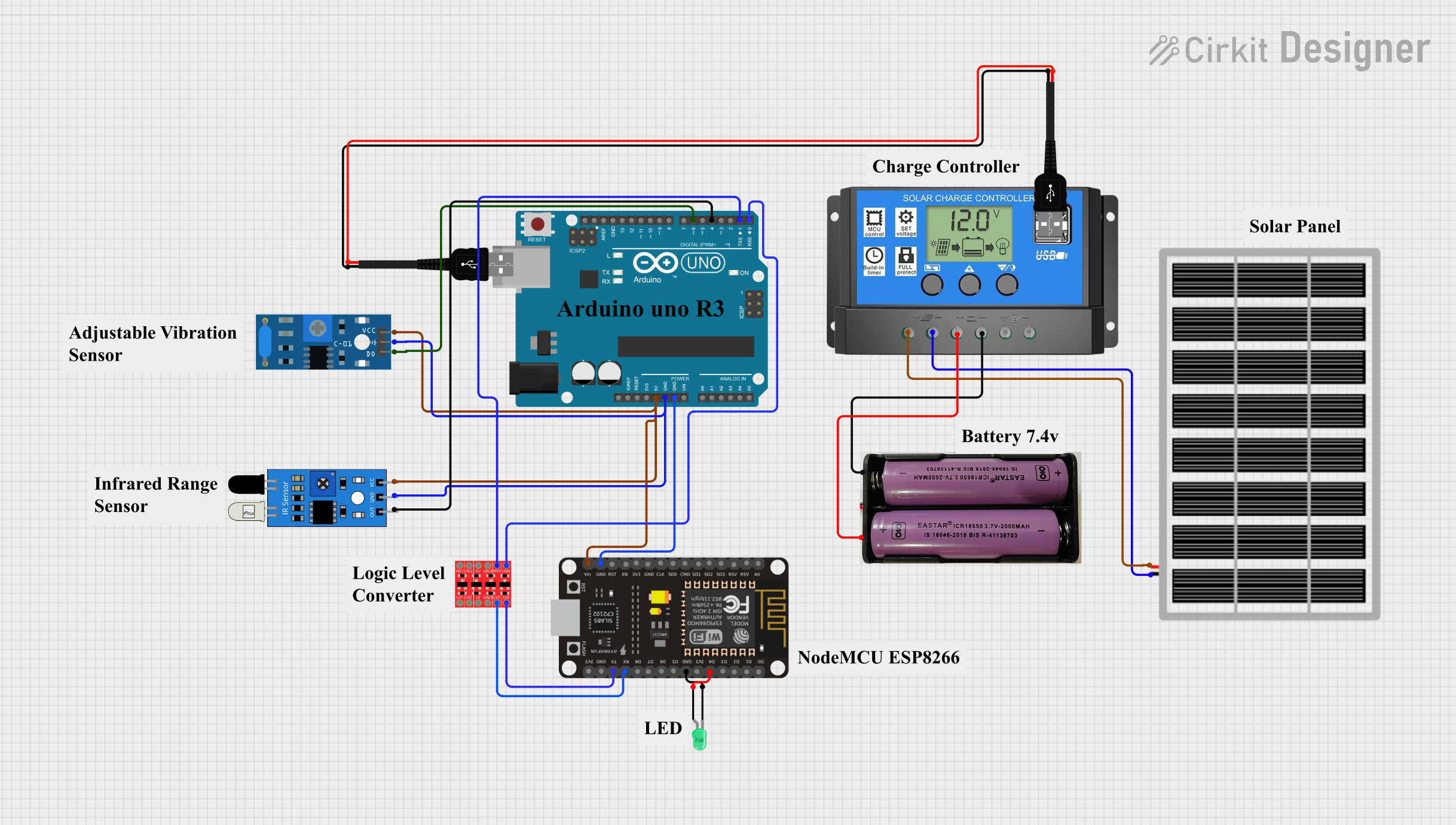
4. Example Code for Arduino UNO
Here is an example code to read an analog sensor connected to the INDUSBOARD V2 and send the data over the serial interface:
// Define the analog input pin
const int analogPin = A0;

// Variable to store the sensor value
int sensorValue = 0;

void setup() {
  // Initialize the serial communication at 9600 baud rate
  Serial.begin(9600);
}

void loop() {
  // Read the analog value from the sensor
  sensorValue = analogRead(analogPin);

  // Print the sensor value to the serial monitor
  Serial.print("Sensor Value: ");
  Serial.println(sensorValue);

  // Wait for 500 milliseconds before the next reading
  delay(500);
}
5. Troubleshooting and FAQs
Common Issues Users Might Face
Board Not Powering On:
- Solution: Check the power supply connections and ensure the input voltage is within the specified range.
No Serial Communication:
- Solution: Verify the connections to the TX and RX pins. Ensure the baud rate in the code matches the serial monitor settings.
Inaccurate Sensor Readings:
- Solution: Check the sensor connections and ensure they are properly connected to the analog input pins. Calibrate the sensors if necessary.
Overheating:
- Solution: Ensure adequate ventilation and consider adding heat sinks or cooling fans if the board operates in high-temperature environments.
FAQs
Q1: Can I use the INDUSBOARD V2 with other microcontrollers?
- A1: Yes, the INDUSBOARD V2 is compatible with various microcontrollers, including Arduino, ESP32, and others. Ensure proper pin mapping and voltage levels.
Q2: How do I update the firmware on the INDUSBOARD V2?
- A2: Firmware updates can be done via the UART interface. Follow the manufacturer's instructions for the update process.
Q3: What is the maximum current the I/O pins can handle?
- A3: The I/O pins can handle a maximum current of 20mA per pin. Exceeding this limit may damage the board.
Q4: Can I use the INDUSBOARD V2 in outdoor environments?
- A4: Yes, but ensure the board is protected from moisture and extreme temperatures. Use appropriate enclosures for outdoor applications.
This documentation provides a comprehensive guide to using the INDUSBOARD V2 in various industrial applications. For further assistance, refer to the manufacturer's support resources or community forums.
Explore Projects Built with INDUSBOARD V2


Explore Projects Built with INDUSBOARD V2