How to Use Arduino Expansion Board: Examples, Pinouts, and Specs
Introduction
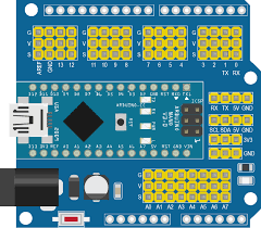
The Arduino Expansion Board, commonly referred to as a "shield," is designed to augment the capabilities of an Arduino board. It connects directly to the Arduino's standard pin headers, providing seamless integration with the base unit. The IO Expansion Board is particularly useful for projects that require additional I/O pins, communication interfaces, or specialized functionality such as motor control, GPS, Ethernet, or wireless communication.
Explore Projects Built with Arduino Expansion Board
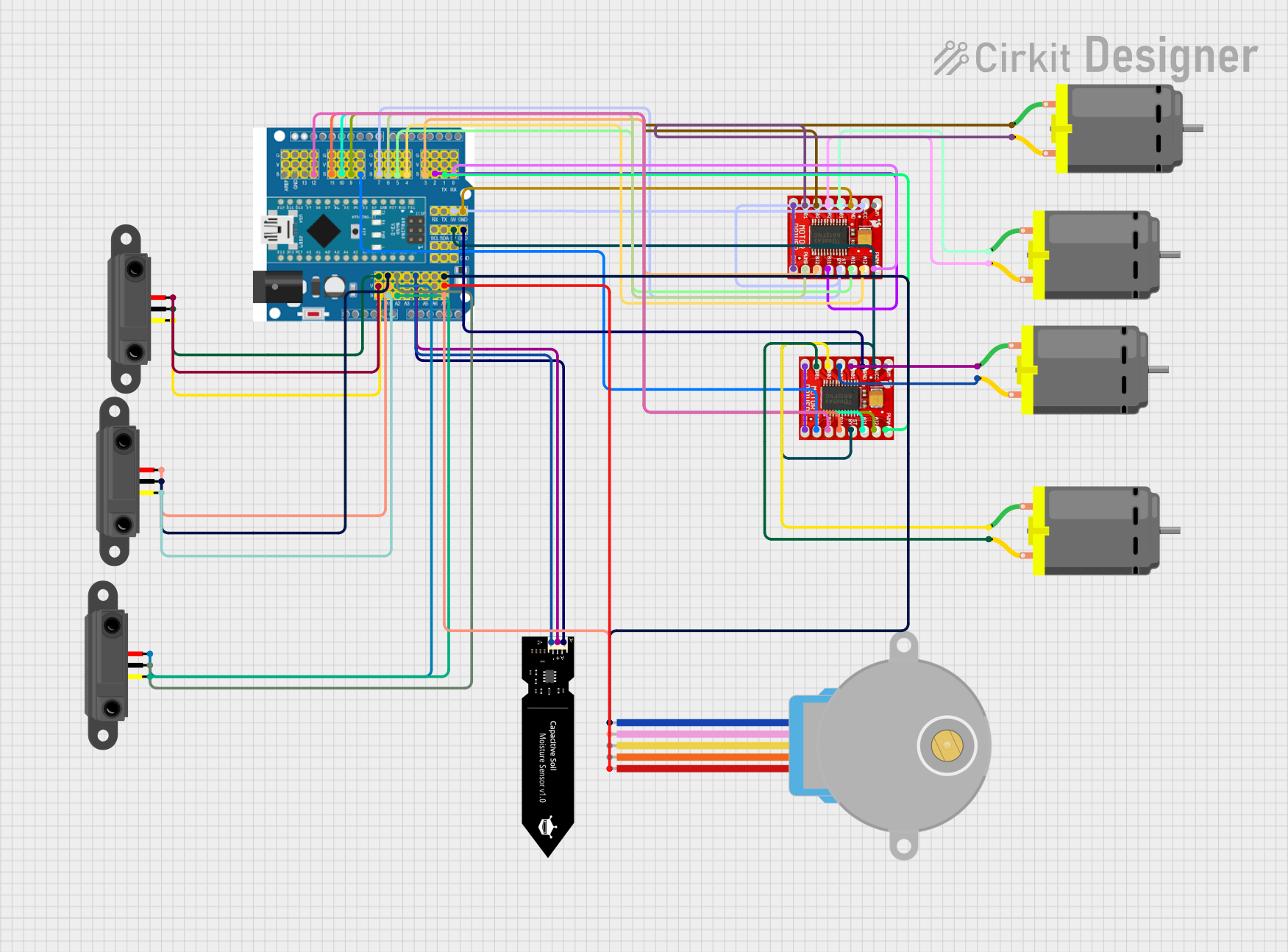
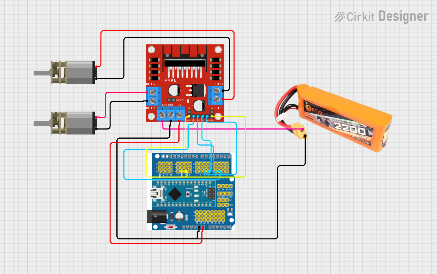
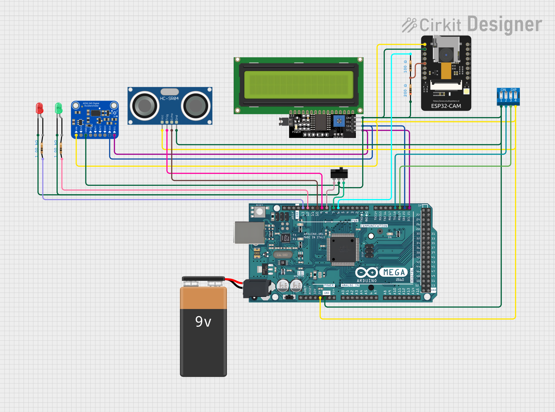

Explore Projects Built with Arduino Expansion Board
Common Applications and Use Cases
- Robotics: Adding motor drivers and sensor interfaces.
- Home Automation: Integrating relays, communication modules, and sensors.
- Data Logging: Expanding connectivity for data storage devices.
- IoT Devices: Incorporating network modules for internet connectivity.
- Prototyping: Quickly adding and testing new circuits or components.
Technical Specifications
Key Technical Details
- Operating Voltage: Compatible with the operating voltage of the connected Arduino board (typically 3.3V or 5V).
- Current Ratings: Varies based on the specific functionalities of the shield.
- Power Ratings: Dependent on the power requirements of the additional components on the shield.
Pin Configuration and Descriptions
| Pin Number | Functionality | Description |
|---|---|---|
| 1 | Digital I/O | Can be configured as input or output pins. |
| 2 | Analog Input | Used for reading analog voltages. |
| 3 | Power (Vcc, GND) | Power supply pins for the shield. |
| 4 | Communication (SPI, I2C, UART) | Pins for serial communication protocols. |
| 5 | Special Function | Pins dedicated to specific functions like PWM, interrupts, etc. |
Note: The actual pin configuration may vary depending on the specific type of IO Expansion Board.
Usage Instructions
How to Use the Component in a Circuit
- Power Off: Ensure the Arduino and the expansion board are powered off before connecting them.
- Align Pins: Carefully align the expansion board's pins with the corresponding headers on the Arduino.
- Connect: Gently press the expansion board down to mate with the Arduino headers.
- Secure (if necessary): Some shields may have additional hardware to secure them to the Arduino (e.g., screws, standoffs).
- Power On: Once securely connected, power on the Arduino.
Important Considerations and Best Practices
- Shield Compatibility: Verify that the shield is compatible with your Arduino model.
- Stacking Shields: Some shields are designed to be stackable. Ensure proper stacking order for compatibility.
- Power Requirements: Check the power requirements of the shield and ensure the Arduino can supply sufficient current.
- Library Installation: Some shields require specific libraries. Install them using the Arduino IDE's Library Manager.
- Pin Usage: Be aware of which pins the shield uses to avoid conflicts with other components in your project.
Example Code for Arduino UNO
// Example code to demonstrate basic usage of an IO Expansion Board with an Arduino UNO
#include <ShieldLibrary.h> // Replace with the actual library for your shield

void setup() {
  // Initialize the shield
  Shield.begin();

  // Configure pins if necessary (e.g., as output)
  pinMode(10, OUTPUT); // Example pin
}

void loop() {
  // Example usage of a shield function
  Shield.doSomething();

  // Control an output pin
  digitalWrite(10, HIGH); // Set pin 10 high
  delay(1000);            // Wait for 1 second
  digitalWrite(10, LOW);  // Set pin 10 low
  delay(1000);            // Wait for 1 second
}
Note: Replace ShieldLibrary.h and Shield with the actual library and object instance for your specific expansion board.
Troubleshooting and FAQs
Common Issues
- Shield Not Recognized: Ensure the shield is properly seated on the Arduino and that there are no bent pins.
- Unexpected Behavior: Check for pin conflicts between the shield and other components in your circuit.
- Library Errors: Verify that you have installed the correct library and that it is up to date.
Solutions and Tips for Troubleshooting
- Re-seat the Shield: Power off the Arduino, remove the shield, and reconnect it, ensuring all pins are aligned.
- Check for Updates: Make sure you have the latest version of the Arduino IDE and any required libraries.
- Review Documentation: Refer to the shield's datasheet and user manual for specific troubleshooting steps.
FAQs
Q: Can I use multiple shields at the same time? A: Yes, as long as the shields are stackable and do not have conflicting pin assignments.
Q: How do I know if a shield is compatible with my Arduino? A: Check the shield's documentation for compatibility information or consult the manufacturer's website.
Q: What should I do if a shield requires more power than the Arduino can provide? A: Use an external power supply that meets the shield's voltage and current requirements, ensuring to share a common ground with the Arduino.