How to Use TTL Converter: Examples, Pinouts, and Specs
Introduction
A TTL (Transistor-Transistor Logic) Converter is a device that converts TTL signal levels to other voltage levels, enabling compatibility between different types of digital circuits. TTL logic levels typically operate at 5V for a high signal and 0V for a low signal. However, many modern digital circuits operate at different voltage levels, such as 3.3V, 2.5V, or even 1.8V. The TTL Converter ensures that these different systems can communicate effectively without damaging the components.
Explore Projects Built with TTL Converter


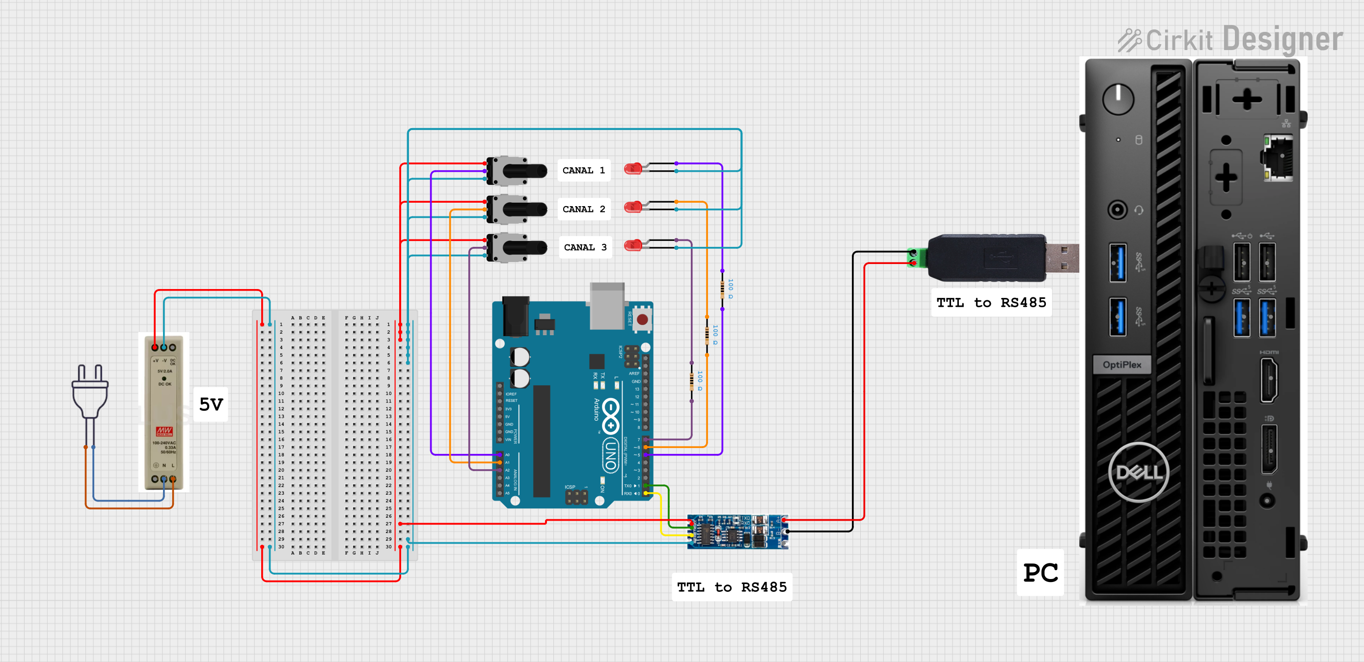
Explore Projects Built with TTL Converter
Common Applications and Use Cases
- Microcontroller Interfacing: Connecting microcontrollers operating at different voltage levels.
- Sensor Integration: Interfacing sensors that operate at different voltage levels with a microcontroller.
- Communication Protocols: Ensuring compatibility between devices using different communication protocols (e.g., UART, SPI, I2C).
- Level Shifting: General purpose level shifting in mixed-voltage systems.
Technical Specifications
Key Technical Details
| Parameter | Value |
|---|---|
| Input Voltage | 1.8V to 5.5V |
| Output Voltage | 1.8V to 5.5V |
| Maximum Current | 50mA |
| Operating Temperature | -40°C to 85°C |
| Propagation Delay | < 10ns |
| Power Consumption | Low |
Pin Configuration and Descriptions
| Pin Number | Pin Name | Description |
|---|---|---|
| 1 | VCC | Power supply for the converter (1.8V to 5.5V) |
| 2 | GND | Ground |
| 3 | IN1 | Input signal 1 (TTL level) |
| 4 | OUT1 | Output signal 1 (Converted level) |
| 5 | IN2 | Input signal 2 (TTL level) |
| 6 | OUT2 | Output signal 2 (Converted level) |
| 7 | IN3 | Input signal 3 (TTL level) |
| 8 | OUT3 | Output signal 3 (Converted level) |
| 9 | IN4 | Input signal 4 (TTL level) |
| 10 | OUT4 | Output signal 4 (Converted level) |
Usage Instructions
How to Use the Component in a Circuit
Power Supply:
- Connect the VCC pin to the power supply of the desired voltage level (1.8V to 5.5V).
- Connect the GND pin to the ground of the circuit.
Signal Connections:
- Connect the TTL signal to the INx pins (where x is the input number).
- The corresponding OUTx pins will provide the converted signal at the desired voltage level.
Example Circuit:
- Suppose you have a microcontroller operating at 5V and a sensor operating at 3.3V. Connect the microcontroller's output to IN1 and the sensor's input to OUT1. The TTL Converter will shift the 5V signal to 3.3V.
Important Considerations and Best Practices
- Voltage Levels: Ensure that the input and output voltage levels are within the specified range (1.8V to 5.5V).
- Current Limiting: Do not exceed the maximum current rating of 50mA to avoid damaging the converter.
- Temperature Range: Operate the converter within the specified temperature range (-40°C to 85°C) for optimal performance.
- Noise Reduction: Use decoupling capacitors close to the VCC pin to reduce noise and ensure stable operation.
Troubleshooting and FAQs
Common Issues Users Might Face
No Output Signal:
- Solution: Check the power supply connections (VCC and GND). Ensure that the input signal is within the specified voltage range.
Incorrect Output Voltage:
- Solution: Verify that the VCC pin is connected to the correct voltage level. Ensure that the input signal is a valid TTL level.
Intermittent Operation:
- Solution: Use decoupling capacitors close to the VCC pin to reduce noise. Check for loose connections or faulty wiring.
Solutions and Tips for Troubleshooting
- Check Connections: Ensure all connections are secure and correctly wired.
- Verify Power Supply: Confirm that the power supply voltage is within the specified range.
- Use Decoupling Capacitors: Place capacitors (e.g., 0.1µF) close to the VCC pin to filter out noise.
- Measure Signals: Use an oscilloscope or multimeter to measure the input and output signals to ensure they are within the expected range.
Example Code for Arduino UNO
// Example code to demonstrate the use of a TTL Converter with Arduino UNO

const int inputPin = 2;  // Pin connected to the TTL Converter's OUT1
const int outputPin = 13; // Pin connected to an LED

void setup() {
  pinMode(inputPin, INPUT);  // Set inputPin as INPUT
  pinMode(outputPin, OUTPUT); // Set outputPin as OUTPUT
  Serial.begin(9600); // Initialize serial communication at 9600 baud
}

void loop() {
  int signal = digitalRead(inputPin); // Read the signal from the TTL Converter
  digitalWrite(outputPin, signal); // Output the signal to the LED
  Serial.println(signal); // Print the signal value to the Serial Monitor
  delay(100); // Delay for 100 milliseconds
}
This example code reads a signal from the TTL Converter and outputs it to an LED connected to pin 13 of the Arduino UNO. The signal value is also printed to the Serial Monitor for debugging purposes.
By following this documentation, users can effectively integrate the TTL Converter into their projects, ensuring compatibility between different voltage levels and enhancing the overall functionality of their digital circuits.