How to Use MT6701 Magnetic Encoder: Examples, Pinouts, and Specs
Introduction
The MT6701 is a high-precision magnetic encoder manufactured by MagnTek. It is designed to provide accurate position and speed feedback by utilizing advanced magnetic sensing technology. This component is widely used in applications requiring precise rotational measurement, such as robotics, motor control, industrial automation, and servo systems. Its compact design and robust performance make it suitable for both consumer and industrial-grade projects.
Explore Projects Built with MT6701 Magnetic Encoder


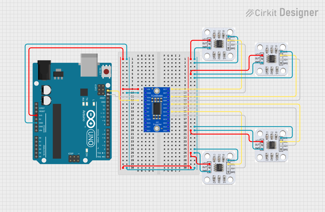
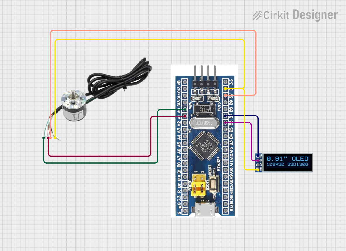
Explore Projects Built with MT6701 Magnetic Encoder
Common Applications
- Robotics and automation systems
- Motor position and speed control
- Industrial machinery and servo systems
- CNC machines and 3D printers
- Automotive applications (e.g., steering and throttle control)
Technical Specifications
The MT6701 offers a range of features and specifications that make it a versatile and reliable choice for magnetic encoding applications.
Key Technical Details
| Parameter | Value |
|---|---|
| Manufacturer | MagnTek |
| Part Number | MT6701 |
| Supply Voltage (VDD) | 3.3V to 5.5V |
| Operating Current | 6 mA (typical) |
| Output Interface | SPI, PWM, ABI (Incremental), UVW |
| Resolution | 12-bit (4096 positions per revolution) |
| Maximum Speed | 60,000 RPM |
| Operating Temperature | -40°C to +125°C |
| Magnetic Field Strength | 30 mT to 70 mT |
| Package Type | TSSOP-16 |
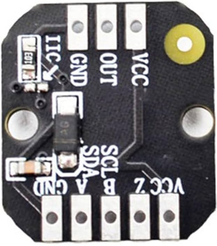
Pin Configuration and Descriptions
The MT6701 comes in a TSSOP-16 package with the following pinout:
| Pin Number | Pin Name | Description |
|---|---|---|
| 1 | VDD | Power supply (3.3V to 5.5V) |
| 2 | GND | Ground |
| 3 | CS | Chip Select for SPI communication |
| 4 | SCK | Serial Clock for SPI |
| 5 | MISO | Master In Slave Out (SPI data output) |
| 6 | MOSI | Master Out Slave In (SPI data input) |
| 7 | PWM | Pulse Width Modulation output |
| 8 | ABI_A | Incremental encoder output (Channel A) |
| 9 | ABI_B | Incremental encoder output (Channel B) |
| 10 | ABI_I | Incremental encoder index pulse |
| 11 | UVW_U | UVW output (Channel U) |
| 12 | UVW_V | UVW output (Channel V) |
| 13 | UVW_W | UVW output (Channel W) |
| 14 | TEST | Factory test pin (leave unconnected) |
| 15 | NC | Not connected |
| 16 | NC | Not connected |
Usage Instructions
The MT6701 can be integrated into a variety of circuits to measure rotational position and speed. Below are the steps and considerations for using the component effectively.
How to Use the MT6701 in a Circuit
- Power Supply: Connect the VDD pin to a 3.3V or 5V power source and the GND pin to ground.
- Magnet Placement: Place a diametrically magnetized magnet above the MT6701 sensor. Ensure the magnetic field strength is within the 30 mT to 70 mT range.
- Output Interface: Choose the desired output interface (SPI, PWM, ABI, or UVW) and connect the corresponding pins to your microcontroller or motor driver.
- SPI Communication: If using SPI, connect the CS, SCK, MISO, and MOSI pins to the appropriate SPI pins on your microcontroller.
- Incremental Outputs: For incremental encoder functionality, connect the ABI_A, ABI_B, and ABI_I pins to your controller.
- UVW Outputs: For motor commutation, connect the UVW_U, UVW_V, and UVW_W pins to the motor driver.
Important Considerations
- Magnet Alignment: Ensure the magnet is properly aligned with the center of the MT6701 for accurate readings.
- Decoupling Capacitor: Place a 0.1 µF decoupling capacitor close to the VDD and GND pins to reduce noise.
- Operating Temperature: Ensure the operating environment is within the specified temperature range (-40°C to +125°C).
- Magnetic Interference: Avoid placing the MT6701 near strong external magnetic fields that could interfere with its operation.
Example Code for Arduino UNO
Below is an example of how to interface the MT6701 with an Arduino UNO using SPI communication:
#include <SPI.h>

// Define SPI pins for MT6701
const int CS_PIN = 10; // Chip Select pin

void setup() {
  // Initialize Serial Monitor
  Serial.begin(9600);

  // Configure SPI settings
  SPI.begin();
  pinMode(CS_PIN, OUTPUT);
  digitalWrite(CS_PIN, HIGH); // Set CS pin high initially
}

uint16_t readMT6701() {
  uint16_t position = 0;

  // Start SPI communication
  digitalWrite(CS_PIN, LOW); // Select the MT6701
  delayMicroseconds(1);      // Small delay for stability

  // Read 2 bytes of data from the MT6701
  position = SPI.transfer(0x00) << 8; // Read high byte
  position |= SPI.transfer(0x00);     // Read low byte

  digitalWrite(CS_PIN, HIGH); // Deselect the MT6701
  return position;
}

void loop() {
  uint16_t position = readMT6701(); // Get position data
  Serial.print("Position: ");
  Serial.println(position); // Print position to Serial Monitor
  delay(100); // Delay for readability
}
Troubleshooting and FAQs
Common Issues and Solutions
No Output or Incorrect Readings
- Cause: Magnet not properly aligned or incorrect magnetic field strength.
- Solution: Reposition the magnet and ensure it is within the specified field strength range (30 mT to 70 mT).
Noise in Output Signals
- Cause: Insufficient decoupling or external electromagnetic interference.
- Solution: Add a 0.1 µF decoupling capacitor near the VDD and GND pins. Minimize exposure to external magnetic fields.
SPI Communication Fails
- Cause: Incorrect SPI wiring or settings.
- Solution: Verify the SPI connections (CS, SCK, MISO, MOSI) and ensure the SPI clock speed is within the MT6701's supported range.
High Power Consumption
- Cause: Incorrect supply voltage or excessive load on output pins.
- Solution: Ensure the supply voltage is within the 3.3V to 5.5V range and avoid overloading the output pins.
FAQs
Q: Can the MT6701 be used with a 3.3V microcontroller?
A: Yes, the MT6701 supports a supply voltage range of 3.3V to 5.5V, making it compatible with 3.3V systems.
Q: What type of magnet should I use with the MT6701?
A: Use a diametrically magnetized magnet with a magnetic field strength between 30 mT and 70 mT.
Q: How do I calculate the angular position from the MT6701's output?
A: The MT6701 provides a 12-bit output, so the angular position can be calculated as:
Angle (degrees) = (Output / 4096) * 360.
Q: Can the MT6701 measure linear motion?
A: No, the MT6701 is designed for rotational position sensing and requires a rotating magnet for operation.