Cirkit Designer
Your all-in-one circuit design IDE
Home /
Component Documentation
How to Use 5pin: Examples, Pinouts, and Specs

 Design with 5pin in Cirkit Designer
Introduction
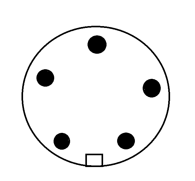
The 5-pin connector is a versatile component commonly used in electronic circuits to provide multiple connection points for signals or power. This connector is essential in various applications, including prototyping, development boards, and interfacing different modules. Its design ensures reliable and secure connections, making it a staple in both hobbyist and professional electronics projects.
Explore Projects Built with 5pin
5-Pin Connector Synchronization Circuit

This circuit consists of four 5-pin connectors, where two of the connectors are fully interconnected pin-to-pin. The purpose of this setup could be to create a parallel connection between the two 5-pin connectors, possibly for signal distribution or redundancy.
 Open Project in Cirkit Designer
Dual 5V Power Supply Distribution Circuit with Toggle Switch Control

This circuit consists of two 5V 5A power supplies connected to an AC wall plug point, providing DC output through a 12-way connector. The ground connections from both power supplies are interconnected and also connected to the ground pins of two toggle switches. The DC outputs from the power supplies are separately connected to different pins on the 12-way connector, with each power supply output being switchable via one of the toggle switches.
 Open Project in Cirkit Designer
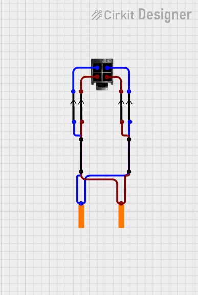
4-Pin Connector Circuit for Edge Detection

This circuit appears to be a simple interconnection of pins and points, with a 4-pin component serving as a central hub. The red and black pins of the 4-pin component are connected to various other pins and edge components, forming a basic network of connections without any active components or microcontroller logic.
 Open Project in Cirkit Designer
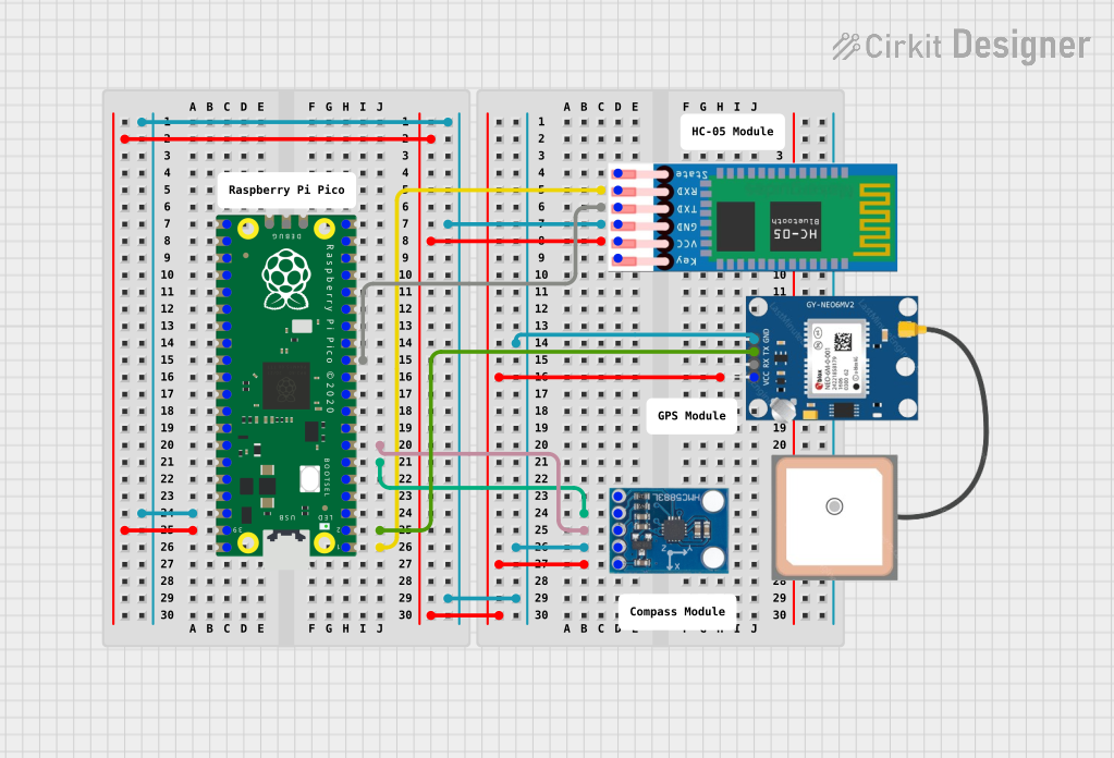
Raspberry Pi Pico-Based Navigation Assistant with Bluetooth and GPS

This circuit features a Raspberry Pi Pico microcontroller interfaced with an HC-05 Bluetooth module for wireless communication, an HMC5883L compass module for magnetic field measurement, and a GPS NEO 6M module for location tracking. The Pico is configured to communicate with the HC-05 via serial connection (TX/RX), with the compass module via I2C (SCL/SDA), and with the GPS module via serial (TX/RX). Common power (VCC) and ground (GND) lines are shared among all modules, indicating a unified power system.
 Open Project in Cirkit Designer
Explore Projects Built with 5pin

5-Pin Connector Synchronization Circuit
This circuit consists of four 5-pin connectors, where two of the connectors are fully interconnected pin-to-pin. The purpose of this setup could be to create a parallel connection between the two 5-pin connectors, possibly for signal distribution or redundancy.
 Open Project in Cirkit Designer
Dual 5V Power Supply Distribution Circuit with Toggle Switch Control
This circuit consists of two 5V 5A power supplies connected to an AC wall plug point, providing DC output through a 12-way connector. The ground connections from both power supplies are interconnected and also connected to the ground pins of two toggle switches. The DC outputs from the power supplies are separately connected to different pins on the 12-way connector, with each power supply output being switchable via one of the toggle switches.
 Open Project in Cirkit Designer
4-Pin Connector Circuit for Edge Detection
This circuit appears to be a simple interconnection of pins and points, with a 4-pin component serving as a central hub. The red and black pins of the 4-pin component are connected to various other pins and edge components, forming a basic network of connections without any active components or microcontroller logic.
 Open Project in Cirkit Designer
Raspberry Pi Pico-Based Navigation Assistant with Bluetooth and GPS
This circuit features a Raspberry Pi Pico microcontroller interfaced with an HC-05 Bluetooth module for wireless communication, an HMC5883L compass module for magnetic field measurement, and a GPS NEO 6M module for location tracking. The Pico is configured to communicate with the HC-05 via serial connection (TX/RX), with the compass module via I2C (SCL/SDA), and with the GPS module via serial (TX/RX). Common power (VCC) and ground (GND) lines are shared among all modules, indicating a unified power system.
 Open Project in Cirkit Designer
Common Applications and Use Cases
- Prototyping and Development Boards: Frequently used in breadboards and development boards like Arduino for easy connections.
- Interfacing Modules: Connecting sensors, displays, and other modules to microcontrollers.
- Power Distribution: Distributing power to multiple components in a circuit.
- Signal Transmission: Transmitting data signals between different parts of a circuit.
Technical Specifications
Key Technical Details
| Specification | Value |
|---|---|
| Number of Pins | 5 |
| Pin Spacing | 2.54 mm (0.1 inch) |
| Current Rating | Up to 3A per pin |
| Voltage Rating | Up to 250V |
| Contact Resistance | ≤ 20 mΩ |
| Insulation Resistance | ≥ 1000 MΩ |
| Operating Temperature | -40°C to +105°C |
Pin Configuration and Descriptions
| Pin Number | Description | Typical Use Case |
|---|---|---|
| 1 | VCC | Power supply (e.g., 5V) |
| 2 | GND | Ground |
| 3 | Signal 1 | Data or control signal |
| 4 | Signal 2 | Data or control signal |
| 5 | Signal 3 | Data or control signal |
Usage Instructions
How to Use the Component in a Circuit
- Identify the Pins: Ensure you correctly identify each pin based on the pin configuration table.
- Connect Power and Ground: Connect the VCC pin to your power source and the GND pin to the ground.
- Connect Signal Pins: Use the remaining pins (Signal 1, Signal 2, Signal 3) to connect to your desired signals or data lines.
- Secure Connections: Ensure all connections are secure to prevent intermittent connections or shorts.
Important Considerations and Best Practices
- Check Pinout: Always double-check the pinout to avoid incorrect connections.
- Current and Voltage Ratings: Ensure the current and voltage ratings are not exceeded to prevent damage.
- Secure Connections: Use proper connectors or soldering techniques to ensure reliable connections.
- Avoid Shorts: Be cautious of potential shorts, especially in high-density circuits.
Example: Connecting to an Arduino UNO
Here is an example of how to connect a 5-pin connector to an Arduino UNO:
// Example code to read data from a sensor connected via a 5-pin connector

const int signalPin1 = 2; // Pin connected to Signal 1
const int signalPin2 = 3; // Pin connected to Signal 2
const int signalPin3 = 4; // Pin connected to Signal 3

void setup() {
  Serial.begin(9600); // Initialize serial communication
  pinMode(signalPin1, INPUT); // Set Signal 1 pin as input
  pinMode(signalPin2, INPUT); // Set Signal 2 pin as input
  pinMode(signalPin3, INPUT); // Set Signal 3 pin as input
}

void loop() {
  int value1 = digitalRead(signalPin1); // Read value from Signal 1
  int value2 = digitalRead(signalPin2); // Read value from Signal 2
  int value3 = digitalRead(signalPin3); // Read value from Signal 3

  // Print the values to the Serial Monitor
  Serial.print("Signal 1: ");
  Serial.println(value1);
  Serial.print("Signal 2: ");
  Serial.println(value2);
  Serial.print("Signal 3: ");
  Serial.println(value3);

  delay(1000); // Wait for 1 second before next read
}
Troubleshooting and FAQs
Common Issues Users Might Face
Intermittent Connections:
- Solution: Ensure all connections are secure and properly soldered or crimped.
Incorrect Pin Connections:
- Solution: Double-check the pin configuration and ensure correct connections.
Exceeding Current/Voltage Ratings:
- Solution: Verify that the current and voltage ratings are within the specified limits.
Signal Interference:
- Solution: Use proper shielding and grounding techniques to minimize interference.
Solutions and Tips for Troubleshooting
- Use a Multimeter: Check continuity and voltage levels to ensure proper connections.
- Inspect Connectors: Look for any signs of damage or wear on the connectors.
- Check Power Supply: Ensure the power supply is stable and within the required specifications.
- Review Code: If using with a microcontroller, ensure the code is correctly configured for the pins used.
By following this documentation, users can effectively utilize the 5-pin connector in their electronic projects, ensuring reliable and efficient connections.