How to Use Adafruit GA1A1S202WP: Examples, Pinouts, and Specs
Introduction
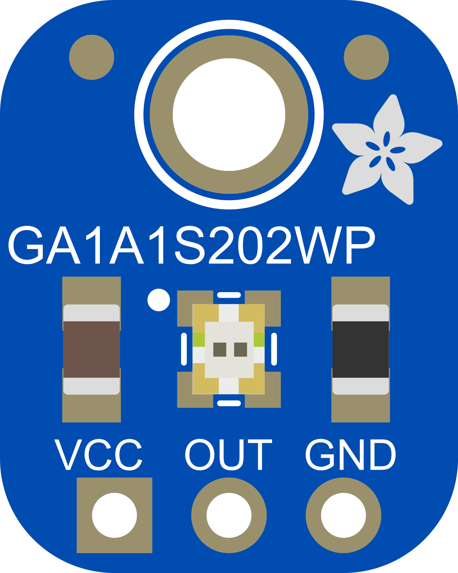
The Adafruit GA1A1S202WP is an analog light sensor module that provides a simple way to integrate light sensing capabilities into a wide range of electronic projects. This sensor is particularly useful for applications that require automatic adjustment of brightness in displays, activation of lighting systems in response to environmental light changes, and for creating energy-efficient devices that respond to ambient light conditions.
Explore Projects Built with Adafruit GA1A1S202WP

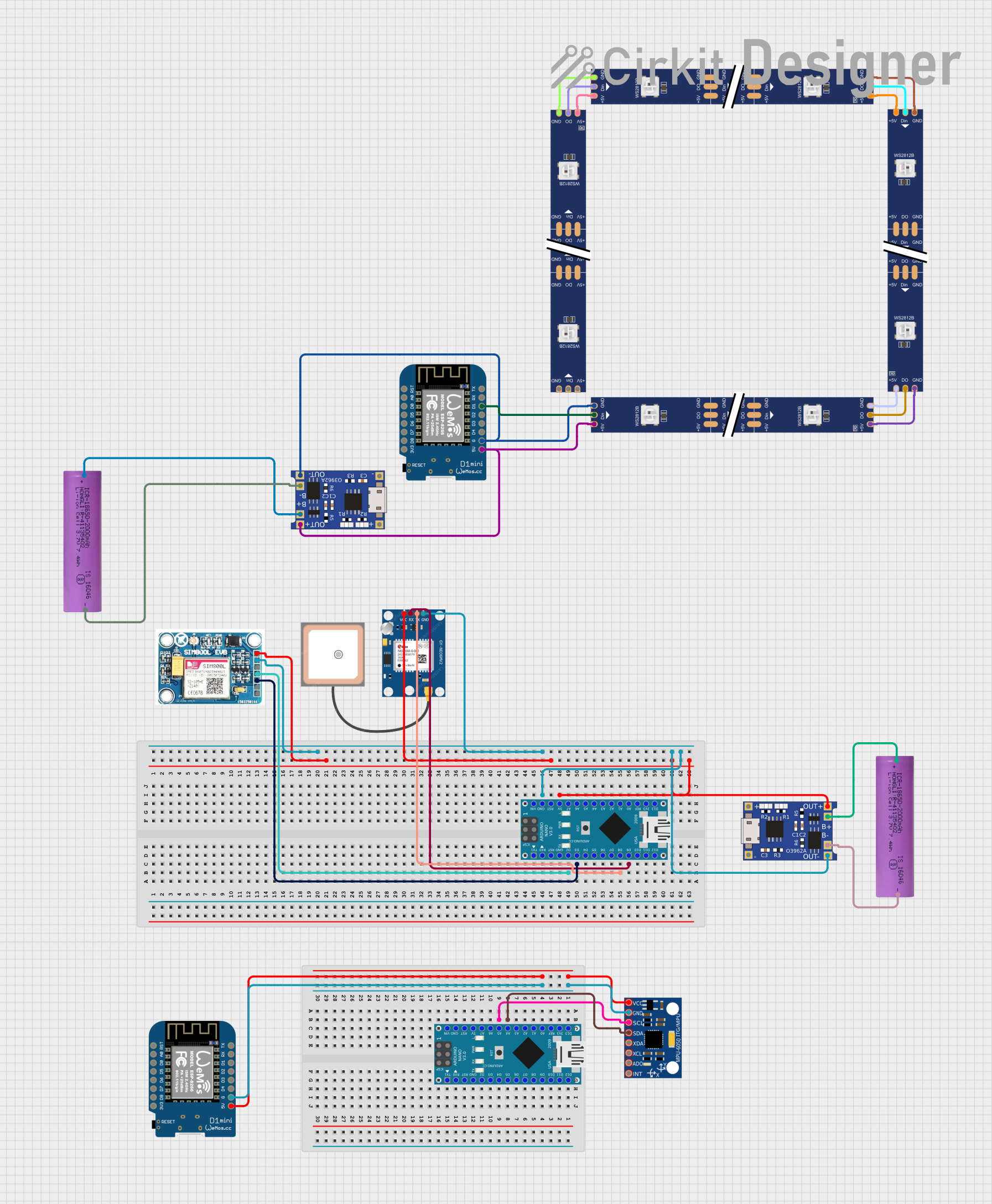


Explore Projects Built with Adafruit GA1A1S202WP
Common Applications
- Automatic brightness control for LCDs and LEDs
- Light-activated alarms and switches
- Environmental monitoring
- Energy-saving lighting systems
Technical Specifications
Key Technical Details
- Supply Voltage: 2.5V to 5.5V
- Output Voltage: 0V to Vcc (proportional to light intensity)
- Operating Temperature: -30°C to 85°C
- Spectral Response: Similar to human eye response
- Dimensions: 20mm x 20mm x 2mm (LxWxH)
Pin Configuration and Descriptions
| Pin Number | Name | Description |
|---|---|---|
| 1 | Vcc | Power supply (2.5V to 5.5V) |
| 2 | OUT | Analog voltage output |
| 3 | GND | Ground |
Usage Instructions
How to Use the Component in a Circuit
- Connect the Vcc pin to a power supply between 2.5V and 5.5V.
- Connect the GND pin to the ground of your power supply.
- Connect the OUT pin to an analog input on your microcontroller (e.g., Arduino UNO).
Important Considerations and Best Practices
- Ensure that the power supply voltage does not exceed the maximum rating of 5.5V to prevent damage to the sensor.
- The output is linearly proportional to the logarithm of the light intensity, which means it has a wide dynamic range.
- Use a pull-down resistor if necessary to ensure a stable reading when the light intensity is very low.
- Avoid exposing the sensor to direct sunlight or high-intensity light sources that could saturate the sensor.
Example Code for Arduino UNO
// Define the analog pin connected to the light sensor
const int lightSensorPin = A0;

void setup() {
  // Initialize serial communication at 9600 bits per second
  Serial.begin(9600);
}

void loop() {
  // Read the input on the analog pin (value between 0 and 1023)
  int sensorValue = analogRead(lightSensorPin);
  // Convert the analog reading to voltage (value between 0 and 5V)
  float voltage = sensorValue * (5.0 / 1023.0);
  // Print out the voltage
  Serial.println(voltage);
  // Wait for 1 second before the next loop
  delay(1000);
}
Troubleshooting and FAQs
Common Issues
- Inaccurate Readings: Ensure that the sensor is not exposed to direct light sources that can cause saturation.
- No Output Voltage: Check the connections and ensure that the Vcc and GND are properly connected.
- Fluctuating Readings: Use a pull-down resistor or a capacitor to filter the noise.
Solutions and Tips for Troubleshooting
- If the sensor provides no output, verify that the power supply is within the specified range and that all connections are secure.
- For fluctuating readings, consider averaging multiple readings to obtain a stable value.
- Ensure that the sensor is mounted in a stable position and is not affected by external vibrations or movements.
FAQs
Q: Can the sensor be used outdoors? A: Yes, but it should not be exposed to harsh weather conditions or direct sunlight that may damage the sensor.
Q: What is the sensitivity range of the sensor? A: The sensor has a wide dynamic range and is sensitive to a broad spectrum of light intensities, but it is most responsive to light levels similar to those perceived by the human eye.
Q: How do I calibrate the sensor for accurate readings? A: Calibration can be done by comparing the sensor output to a known light source and adjusting the readings accordingly in your code.
Q: Is it possible to connect multiple sensors to a single microcontroller? A: Yes, multiple sensors can be connected to different analog pins on a microcontroller. Ensure that each sensor has its own dedicated analog input pin.