
How to Use Rhino MDD20Amp 6V-30V Dual DC Motor Driver (2 Channels): Examples, Pinouts, and Specs
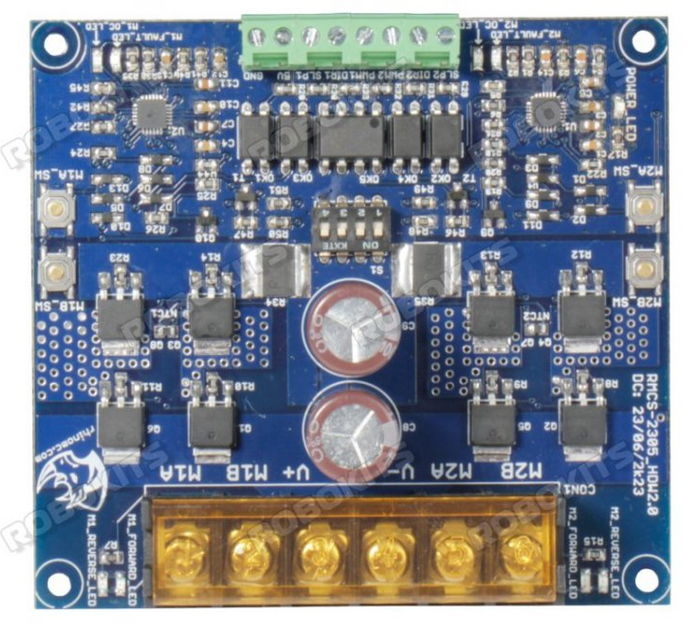
 Design with Rhino MDD20Amp 6V-30V Dual DC Motor Driver (2 Channels) in Cirkit Designer
Introduction
The Rhino MDD20Amp 6V-30V Dual DC Motor Driver is a high-performance motor driver designed to control two DC motors simultaneously. With a current rating of 20 Amps per channel and an operating voltage range of 6V to 30V, this motor driver is ideal for robotics, automation, and other motor control applications. Its robust design ensures reliable operation in demanding environments, making it a popular choice for hobbyists and professionals alike.
Explore Projects Built with Rhino MDD20Amp 6V-30V Dual DC Motor Driver (2 Channels)
 Open Project in Cirkit Designer
 Open Project in Cirkit Designer
 Open Project in Cirkit Designer
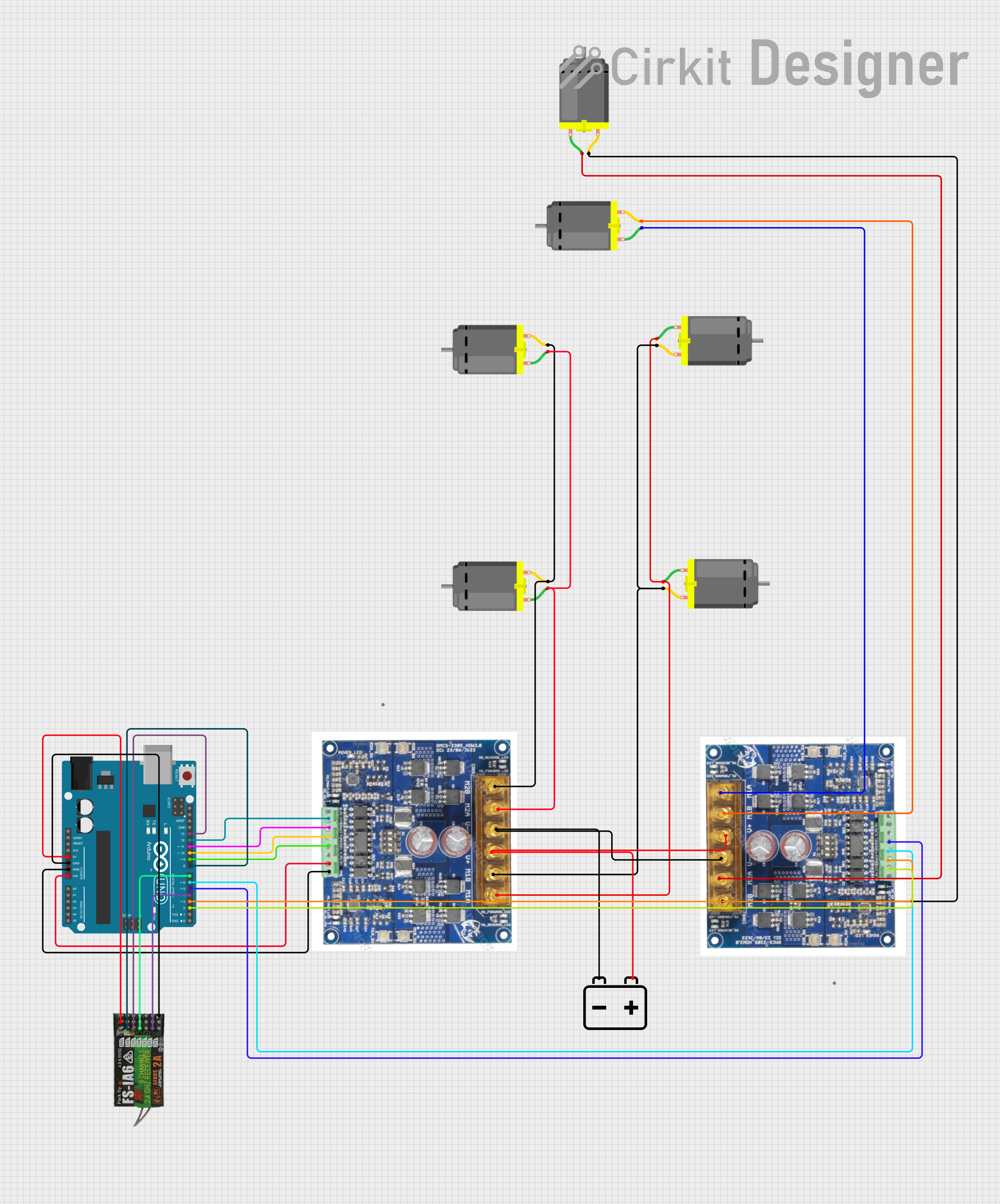 Open Project in Cirkit Designer
Explore Projects Built with Rhino MDD20Amp 6V-30V Dual DC Motor Driver (2 Channels)
Open Project in Cirkit DesignerOpen Project in Cirkit DesignerOpen Project in Cirkit DesignerOpen Project in Cirkit DesignerCommon Applications
- Robotics (e.g., controlling robot wheels or arms)
- Automated guided vehicles (AGVs)
- Conveyor belt systems
- Electric scooters and carts
- Industrial automation systems
Technical Specifications
Below are the key technical details of the Rhino MDD20Amp motor driver:
| Parameter | Specification |
|---|---|
| Manufacturer | Rhino |
| Part ID | Motor Driver |
| Channels | 2 (Dual-channel) |
| Operating Voltage Range | 6V to 30V |
| Continuous Current | 20A per channel |
| Peak Current | 50A per channel (for short durations) |
| Control Logic Voltage | 3.3V to 5V |
| PWM Frequency | Up to 20 kHz |
| Dimensions | 60mm x 55mm x 15mm |
| Weight | 50g |
Pin Configuration and Descriptions
The Rhino MDD20Amp motor driver has the following pin layout:
| Pin Name | Type | Description |
|---|---|---|
| VIN | Power Input | Connect to the motor power supply (6V to 30V). |
| GND | Ground | Common ground for power and logic. |
| INA1 | Logic Input | Input signal to control the direction of Motor A. |
| INB1 | Logic Input | Input signal to control the direction of Motor B. |
| PWM1 | PWM Input | Pulse Width Modulation input for speed control of Motor A. |
| PWM2 | PWM Input | Pulse Width Modulation input for speed control of Motor B. |
| OUTA+ | Motor Output | Positive terminal for Motor A. |
| OUTA- | Motor Output | Negative terminal for Motor A. |
| OUTB+ | Motor Output | Positive terminal for Motor B. |
| OUTB- | Motor Output | Negative terminal for Motor B. |
Usage Instructions
How to Use the Component in a Circuit
- Power Supply: Connect the VIN pin to a DC power supply (6V to 30V) capable of providing sufficient current for your motors. Connect the GND pin to the power supply ground.
- Motor Connections: Connect the motor terminals to the OUTA+/OUTA- pins for Motor A and OUTB+/OUTB- pins for Motor B.
- Logic Control: Use a microcontroller (e.g., Arduino UNO) to send control signals to the INA1, INB1, PWM1, and PWM2 pins. Ensure the logic voltage is within the 3.3V to 5V range.
- PWM Control: Use PWM signals on the PWM1 and PWM2 pins to control the speed of Motor A and Motor B, respectively. The duty cycle of the PWM signal determines the motor speed.
- Direction Control: Use INA1 and INB1 to set the direction of the motors:
- INA1 = HIGH, INB1 = LOW: Forward direction for Motor A.
- INA1 = LOW, INB1 = HIGH: Reverse direction for Motor A.
- Similarly, use INA2 and INB2 for Motor B.
Important Considerations and Best Practices
- Ensure the power supply can handle the combined current requirements of both motors.
- Use appropriate heat sinks or cooling mechanisms if operating at high currents for extended periods.
- Avoid reversing the polarity of the power supply to prevent damage to the motor driver.
- Use capacitors across the motor terminals to reduce electrical noise and improve performance.
- Always test the motor driver with a lower current load before connecting high-power motors.
Example Code for Arduino UNO
Below is an example code snippet to control two DC motors using the Rhino MDD20Amp motor driver and an Arduino UNO:
// Define motor control pins
const int INA1 = 2;  // Direction control for Motor A
const int INB1 = 3;  // Direction control for Motor A
const int PWM1 = 5;  // Speed control for Motor A (PWM)

const int INA2 = 4;  // Direction control for Motor B
const int INB2 = 7;  // Direction control for Motor B
const int PWM2 = 6;  // Speed control for Motor B (PWM)

void setup() {
  // Set motor control pins as outputs
  pinMode(INA1, OUTPUT);
  pinMode(INB1, OUTPUT);
  pinMode(PWM1, OUTPUT);

  pinMode(INA2, OUTPUT);
  pinMode(INB2, OUTPUT);
  pinMode(PWM2, OUTPUT);
}

void loop() {
  // Example: Run Motor A forward at 50% speed
  digitalWrite(INA1, HIGH);  // Set direction forward
  digitalWrite(INB1, LOW);
  analogWrite(PWM1, 128);    // Set speed (128/255 = 50%)

  // Example: Run Motor B backward at 75% speed
  digitalWrite(INA2, LOW);   // Set direction backward
  digitalWrite(INB2, HIGH);
  analogWrite(PWM2, 192);    // Set speed (192/255 = 75%)

  delay(5000);               // Run for 5 seconds

  // Stop both motors
  analogWrite(PWM1, 0);      // Stop Motor A
  analogWrite(PWM2, 0);      // Stop Motor B
  delay(2000);               // Wait for 2 seconds
}
Troubleshooting and FAQs
Common Issues and Solutions
Motors Not Running
- Cause: Incorrect wiring or insufficient power supply.
- Solution: Double-check all connections and ensure the power supply meets the voltage and current requirements.
Overheating
- Cause: Prolonged operation at high currents without proper cooling.
- Solution: Add heat sinks or active cooling (e.g., fans) to the motor driver.
Erratic Motor Behavior
- Cause: Electrical noise or unstable power supply.
- Solution: Add decoupling capacitors across the motor terminals and use a stable power source.
PWM Signal Not Working
- Cause: Incorrect PWM frequency or duty cycle.
- Solution: Ensure the PWM frequency is within the supported range (up to 20 kHz) and adjust the duty cycle as needed.
FAQs
Can I use this motor driver with a 3.3V microcontroller?
- Yes, the control logic voltage range is 3.3V to 5V, making it compatible with 3.3V microcontrollers.
What happens if I exceed the 20A current rating?
- The motor driver can handle up to 50A peak current for short durations, but prolonged operation above 20A may cause overheating or damage.
Is reverse polarity protection included?
- No, the motor driver does not have built-in reverse polarity protection. Ensure correct polarity when connecting the power supply.
Can I control brushless motors with this driver?
- No, this motor driver is designed for brushed DC motors only.
By following this documentation, you can effectively integrate the Rhino MDD20Amp motor driver into your projects and troubleshoot common issues with ease.