How to Use DFRobot DFR1073 GP8413 0-5V/10V 15-bit: Examples, Pinouts, and Specs
Introduction
The DFRobot DFR1073 GP8413 is a high-resolution analog-to-digital converter (ADC) designed for precise voltage measurements in electronic systems. With support for input voltage ranges of 0-5V and 0-10V, and a 15-bit resolution, this ADC is ideal for applications requiring accurate and reliable data acquisition. Its compact design and versatile functionality make it suitable for use in industrial automation, sensor interfacing, and scientific instrumentation.
Explore Projects Built with DFRobot DFR1073 GP8413 0-5V/10V 15-bit

Explore Projects Built with DFRobot DFR1073 GP8413 0-5V/10V 15-bit
Common Applications and Use Cases
- Sensor data acquisition (e.g., temperature, pressure, or light sensors)
- Industrial process monitoring and control
- Precision voltage measurement in laboratory equipment
- IoT devices requiring high-resolution analog input
- Robotics and automation systems
Technical Specifications
The DFRobot DFR1073 GP8413 ADC offers the following key technical details:
| Parameter | Specification |
|---|---|
| Input Voltage Range | 0-5V / 0-10V (selectable) |
| Resolution | 15-bit |
| Sampling Rate | Up to 860 samples per second |
| Communication Interface | I2C |
| Operating Voltage | 3.3V / 5V |
| Operating Current | < 5mA |
| Dimensions | 22mm x 32mm |
| Operating Temperature | -40°C to 85°C |
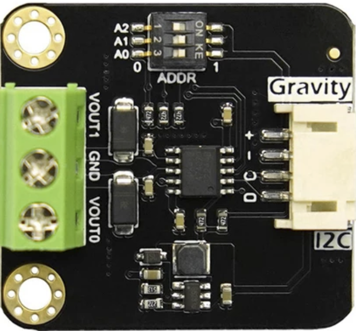
Pin Configuration and Descriptions
The DFRobot DFR1073 GP8413 features a simple pinout for easy integration into circuits:
| Pin | Name | Description |
|---|---|---|
| 1 | VCC | Power supply input (3.3V or 5V) |
| 2 | GND | Ground connection |
| 3 | SDA | I2C data line |
| 4 | SCL | I2C clock line |
| 5 | ADDR | I2C address selection (connect to GND or VCC) |
| 6 | VIN | Analog input voltage (0-5V or 0-10V, selectable) |
Usage Instructions
How to Use the Component in a Circuit
- Power Supply: Connect the VCC pin to a 3.3V or 5V power source and the GND pin to the ground.
- I2C Communication: Connect the SDA and SCL pins to the corresponding I2C pins on your microcontroller (e.g., Arduino UNO).
- Input Voltage: Connect the voltage to be measured to the VIN pin. Ensure the input voltage does not exceed the selected range (0-5V or 0-10V).
- I2C Address Selection: Use the ADDR pin to set the I2C address. Connect it to GND for the default address or to VCC for an alternate address.
- Voltage Range Selection: Configure the input voltage range (0-5V or 0-10V) using the onboard jumper or switch (refer to the product datasheet for details).
Important Considerations and Best Practices
- Ensure the input voltage does not exceed the selected range to avoid damaging the ADC.
- Use appropriate pull-up resistors (typically 4.7kΩ) on the SDA and SCL lines for reliable I2C communication.
- Keep the input signal free from noise by using proper shielding and grounding techniques.
- If using the ADC with an Arduino UNO, ensure the I2C address matches the one configured on the ADDR pin.
Example Code for Arduino UNO
Below is an example Arduino sketch to read data from the DFRobot DFR1073 GP8413 ADC:
#include <Wire.h> // Include the Wire library for I2C communication

#define ADC_I2C_ADDRESS 0x48 // Default I2C address of the ADC

void setup() {
  Wire.begin(); // Initialize I2C communication
  Serial.begin(9600); // Start serial communication for debugging
  Serial.println("DFR1073 ADC Example");
}

void loop() {
  Wire.beginTransmission(ADC_I2C_ADDRESS); // Start communication with ADC
  Wire.write(0x00); // Request data from the ADC
  Wire.endTransmission();

  Wire.requestFrom(ADC_I2C_ADDRESS, 2); // Request 2 bytes of data
  if (Wire.available() == 2) {
    uint16_t rawData = (Wire.read() << 8) | Wire.read(); // Combine two bytes
    float voltage = (rawData / 32768.0) * 5.0; // Convert to voltage (0-5V range)
    Serial.print("Voltage: ");
    Serial.print(voltage, 3); // Print voltage with 3 decimal places
    Serial.println(" V");
  }

  delay(500); // Wait for 500ms before the next reading
}
Notes on the Code
- The
ADC_I2C_ADDRESSshould match the address set by the ADDR pin. - The voltage conversion formula assumes a 0-5V input range. Adjust the formula for a 0-10V range if needed.
Troubleshooting and FAQs
Common Issues and Solutions
No Data from the ADC
- Ensure the I2C connections (SDA, SCL) are correct and have pull-up resistors.
- Verify the I2C address matches the one configured on the ADDR pin.
- Check the power supply voltage (VCC) and ensure it is stable.
Incorrect Voltage Readings
- Confirm the input voltage range (0-5V or 0-10V) is correctly configured.
- Ensure the input signal is within the selected range.
- Check for noise or interference in the input signal.
Communication Errors
- Verify the microcontroller's I2C pins are functioning correctly.
- Ensure the I2C clock speed is compatible with the ADC (typically 100kHz or 400kHz).
FAQs
Q: Can I use the DFR1073 with a 3.3V microcontroller?
A: Yes, the ADC supports both 3.3V and 5V logic levels, making it compatible with a wide range of microcontrollers.
Q: How do I change the input voltage range?
A: The input voltage range can be changed using the onboard jumper or switch. Refer to the product datasheet for detailed instructions.
Q: What is the maximum sampling rate of the ADC?
A: The DFR1073 supports a maximum sampling rate of 860 samples per second.
Q: Can I connect multiple DFR1073 modules to the same I2C bus?
A: Yes, you can connect multiple modules by configuring unique I2C addresses using the ADDR pin.
This concludes the documentation for the DFRobot DFR1073 GP8413 ADC. For further assistance, refer to the official DFRobot product page or contact their support team.