
How to Use Header 2: Examples, Pinouts, and Specs
 Design with Header 2 in Cirkit Designer
Introduction
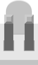
A Header 2 is a type of connector used to interface with printed circuit boards (PCBs). It typically features two rows of pins, making it ideal for secure and reliable connections in electronic circuits. These connectors are widely used in applications requiring modularity, such as prototyping, embedded systems, and interfacing with microcontrollers. Header 2 connectors are available in various pin counts and configurations, making them versatile for a wide range of projects.
Common applications include:
- Connecting peripherals to microcontrollers (e.g., sensors, displays, and modules)
- Prototyping and breadboarding
- Interfacing between PCBs in modular systems
- Providing power and signal connections in embedded systems
Explore Projects Built with Header 2
 Open Project in Cirkit Designer
 Open Project in Cirkit Designer
 Open Project in Cirkit Designer
 Open Project in Cirkit Designer
Explore Projects Built with Header 2
Open Project in Cirkit DesignerOpen Project in Cirkit DesignerOpen Project in Cirkit DesignerOpen Project in Cirkit DesignerTechnical Specifications
Below are the general technical specifications for a standard Header 2 connector. Note that specific values may vary depending on the manufacturer and model.
General Specifications
- Number of Rows: 2
- Pin Pitch: 2.54 mm (standard), other pitches available
- Pin Count: Typically 2x2, 2x4, 2x5, 2x10, etc.
- Current Rating: 1A to 3A per pin (varies by model)
- Voltage Rating: Up to 250V
- Operating Temperature: -40°C to +105°C
- Contact Material: Gold-plated or tin-plated copper alloy
- Mounting Type: Through-hole or surface-mount
Pin Configuration and Descriptions
The pin configuration of a Header 2 connector depends on the specific pin count. Below is an example for a 2x5 (10-pin) Header 2 connector:
| Pin Number | Description | Notes |
|---|---|---|
| 1 | Signal/Power Line 1 | Can be used for data or power |
| 2 | Signal/Power Line 2 | Can be used for data or power |
| 3 | Signal/Power Line 3 | |
| 4 | Signal/Power Line 4 | |
| 5 | Signal/Power Line 5 | |
| 6 | Signal/Power Line 6 | |
| 7 | Signal/Power Line 7 | |
| 8 | Signal/Power Line 8 | |
| 9 | Signal/Power Line 9 | |
| 10 | Signal/Power Line 10 |
Note: The specific pin assignments depend on the application and circuit design.
Usage Instructions
How to Use the Component in a Circuit
- Select the Appropriate Header: Choose a Header 2 connector with the correct pin count and pitch for your application.
- Mounting:
- For through-hole headers, insert the pins into the PCB holes and solder them on the opposite side.
- For surface-mount headers, align the pins with the PCB pads and solder them in place.
- Connect Wires or Components: Use jumper wires, ribbon cables, or mating connectors to interface with the Header 2 pins.
- Verify Connections: Ensure all connections are secure and match the intended circuit design.
Important Considerations and Best Practices
- Pin Alignment: Ensure proper alignment of the header pins with the mating connector or cable to avoid damage.
- Soldering: Use appropriate soldering techniques to avoid cold joints or overheating the pins.
- Current and Voltage Ratings: Do not exceed the specified current and voltage ratings to prevent overheating or failure.
- Strain Relief: Use strain relief mechanisms (e.g., cable ties) to reduce stress on the connections.
Example: Using Header 2 with an Arduino UNO
Header 2 connectors are commonly used to interface with Arduino boards. Below is an example of connecting a 2x5 Header 2 to an Arduino UNO for a simple LED control circuit.
Circuit Setup
- Connect Pin 1 of the Header 2 to the Arduino's digital pin 8.
- Connect Pin 2 of the Header 2 to the ground (GND) pin on the Arduino.
- Connect an LED and a 220-ohm resistor to the corresponding pins on the Header 2.
Arduino Code
// Example code to control an LED connected via a Header 2 connector

const int ledPin = 8; // Pin 1 of Header 2 is connected to digital pin 8

void setup() {
  pinMode(ledPin, OUTPUT); // Set the LED pin as an output
}

void loop() {
  digitalWrite(ledPin, HIGH); // Turn the LED on
  delay(1000);               // Wait for 1 second
  digitalWrite(ledPin, LOW);  // Turn the LED off
  delay(1000);               // Wait for 1 second
}
Troubleshooting and FAQs
Common Issues
Loose Connections:
- Problem: The connection between the Header 2 and the mating connector is loose.
- Solution: Ensure the header pins are properly soldered and the mating connector is securely attached.
Incorrect Pin Mapping:
- Problem: The circuit does not work as expected due to incorrect pin assignments.
- Solution: Double-check the pin mapping and ensure it matches the circuit design.
Overheating:
- Problem: The Header 2 connector overheats during operation.
- Solution: Verify that the current and voltage ratings are not exceeded.
Cold Solder Joints:
- Problem: Poor soldering results in intermittent connections.
- Solution: Re-solder the pins using proper soldering techniques.
FAQs
Q1: Can I use a Header 2 connector for high-frequency signals?
A1: Yes, but ensure the connector's impedance and signal integrity are suitable for the frequency range.
Q2: Are Header 2 connectors compatible with breadboards?
A2: Yes, through-hole Header 2 connectors with a 2.54 mm pitch are compatible with standard breadboards.
Q3: How do I prevent accidental disconnections?
A3: Use locking connectors or secure the mating connector with a cable tie or adhesive.
Q4: Can I use a Header 2 connector for power delivery?
A4: Yes, but ensure the current and voltage ratings of the connector are not exceeded.