How to Use 4 pin led: Examples, Pinouts, and Specs
Introduction
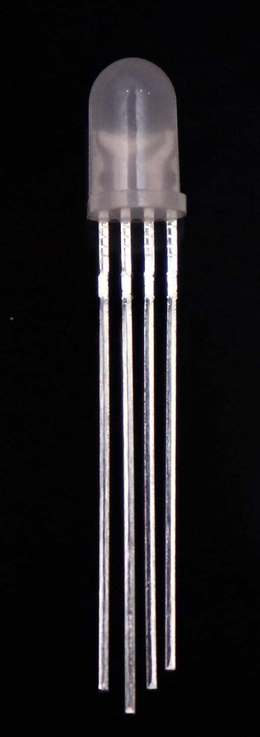
A 4 pin LED (Light Emitting Diode) is a versatile electronic component that emits light when an electric current flows through it. Unlike standard LEDs, the 4 pin LED features additional pins that allow for more advanced functionality, such as controlling multiple colors or adjusting brightness. These LEDs are commonly used in applications requiring dynamic lighting effects, such as RGB lighting, displays, and decorative lighting.
Explore Projects Built with 4 pin led
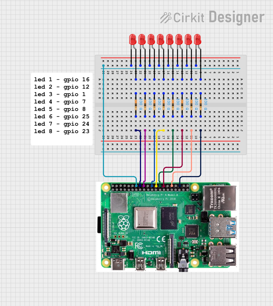


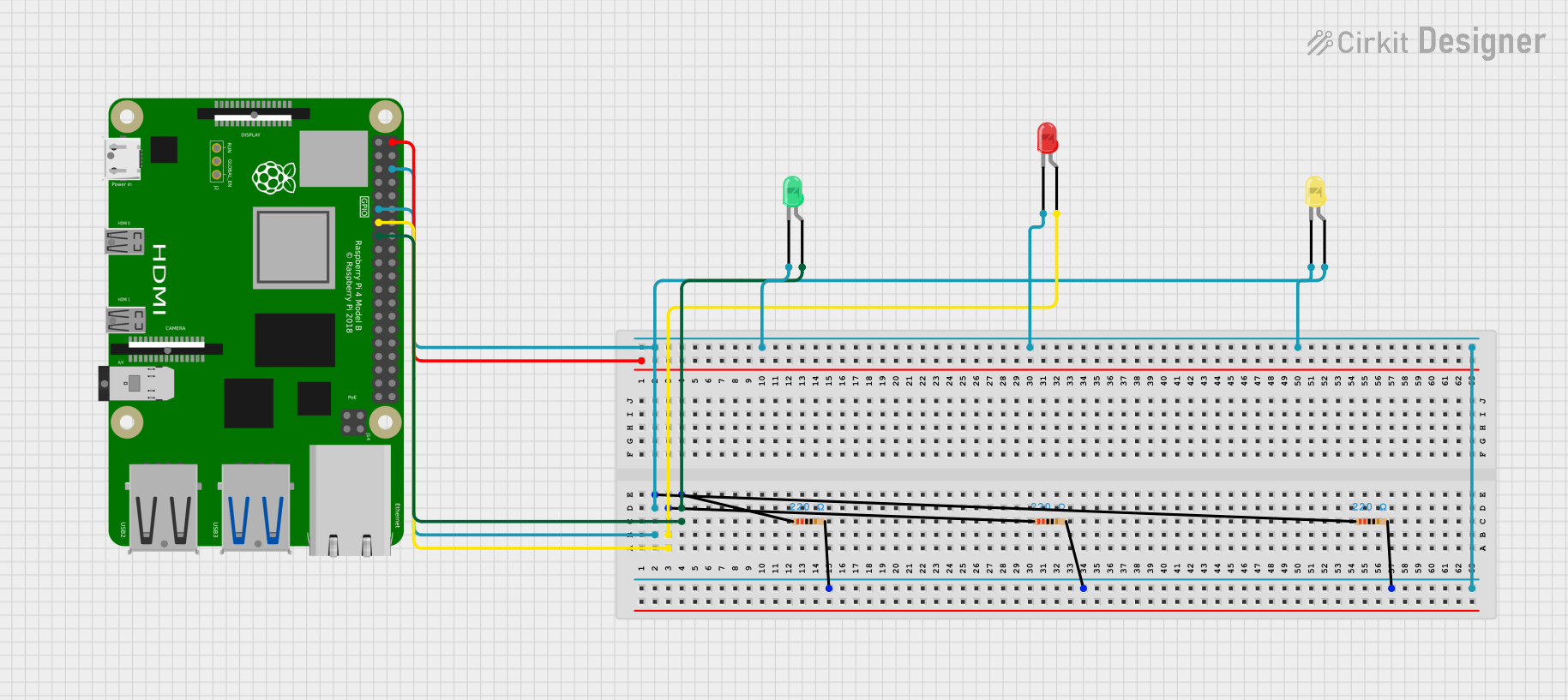
Explore Projects Built with 4 pin led
Common Applications
- RGB (Red, Green, Blue) lighting for decorative purposes
- Status indicators in electronic devices
- Displays and signage
- Mood lighting and smart home systems
- Automotive lighting
Technical Specifications
Key Technical Details
- Forward Voltage: Typically 2.0V to 3.4V (varies by color)
- Red: ~2.0V
- Green: ~3.0V
- Blue: ~3.2V
- Forward Current: 20mA (per color channel)
- Power Dissipation: ~60mW per channel
- Viewing Angle: 120° (typical)
- Lifespan: 50,000+ hours (under proper usage conditions)
Pin Configuration and Descriptions
The 4 pin LED typically has the following pinout:
| Pin Number | Name | Description |
|---|---|---|
| 1 | Cathode (Common) | The shared negative terminal for all internal LEDs. |
| 2 | Red Anode | Positive terminal for the red LED. |
| 3 | Green Anode | Positive terminal for the green LED. |
| 4 | Blue Anode | Positive terminal for the blue LED. |
Note: The pin order may vary depending on the manufacturer. Always refer to the datasheet for your specific 4 pin LED.
Usage Instructions
How to Use the 4 Pin LED in a Circuit
- Identify the Pins: Use the pinout table above or a datasheet to identify the cathode and anode pins.
- Connect Resistors: To prevent damage, connect a current-limiting resistor (typically 220Ω to 330Ω) in series with each anode pin (Red, Green, Blue).
- Power the LED: Connect the cathode pin to the ground (GND) of your power source or microcontroller. Then, connect the anode pins to the appropriate voltage source or microcontroller pins.
- Control Brightness/Color: Use Pulse Width Modulation (PWM) signals on the anode pins to adjust brightness and mix colors.
Example Circuit with Arduino UNO
Below is an example of how to connect and control a 4 pin RGB LED using an Arduino UNO:
Circuit Connections
- Cathode (Pin 1): Connect to GND on the Arduino.
- Red Anode (Pin 2): Connect to Arduino digital pin 9 through a 220Ω resistor.
- Green Anode (Pin 3): Connect to Arduino digital pin 10 through a 220Ω resistor.
- Blue Anode (Pin 4): Connect to Arduino digital pin 11 through a 220Ω resistor.
Arduino Code Example
// Define the pins for the RGB LED
const int redPin = 9;    // Red anode connected to pin 9
const int greenPin = 10; // Green anode connected to pin 10
const int bluePin = 11;  // Blue anode connected to pin 11

void setup() {
  // Set the RGB LED pins as outputs
  pinMode(redPin, OUTPUT);
  pinMode(greenPin, OUTPUT);
  pinMode(bluePin, OUTPUT);
}

void loop() {
  // Example: Cycle through colors
  setColor(255, 0, 0); // Red
  delay(1000);         // Wait 1 second
  setColor(0, 255, 0); // Green
  delay(1000);         // Wait 1 second
  setColor(0, 0, 255); // Blue
  delay(1000);         // Wait 1 second
  setColor(255, 255, 0); // Yellow (Red + Green)
  delay(1000);           // Wait 1 second
  setColor(0, 255, 255); // Cyan (Green + Blue)
  delay(1000);           // Wait 1 second
  setColor(255, 0, 255); // Magenta (Red + Blue)
  delay(1000);           // Wait 1 second
  setColor(255, 255, 255); // White (Red + Green + Blue)
  delay(1000);             // Wait 1 second
}

// Function to set the color of the RGB LED
void setColor(int redValue, int greenValue, int blueValue) {
  analogWrite(redPin, redValue);   // Set red brightness
  analogWrite(greenPin, greenValue); // Set green brightness
  analogWrite(bluePin, blueValue);  // Set blue brightness
}
Important Considerations
- Resistors: Always use appropriate resistors to limit current and prevent damage to the LED.
- PWM Control: Use PWM-capable pins on your microcontroller to control brightness and mix colors.
- Heat Management: Avoid exceeding the maximum current rating to prevent overheating.
Troubleshooting and FAQs
Common Issues and Solutions
The LED does not light up:
- Check the connections and ensure the cathode is connected to GND.
- Verify that the current-limiting resistors are properly connected.
- Ensure the power supply voltage matches the LED's requirements.
Incorrect colors or no color mixing:
- Verify the pin connections for the red, green, and blue anodes.
- Check the PWM signals and ensure they are correctly configured in the code.
LED is dim:
- Ensure the resistors are not too large (e.g., higher than 330Ω).
- Verify the power supply voltage is sufficient.
LED overheats:
- Reduce the current by increasing the resistor values.
- Avoid running the LED at maximum brightness for extended periods.
FAQs
Can I use a 4 pin LED without a microcontroller? Yes, you can use switches or potentiometers to manually control the anode pins, but a microcontroller provides more precise control.
What happens if I connect the LED without resistors? The LED may draw excessive current, leading to overheating and permanent damage.
Can I use a 4 pin LED with a 3.3V microcontroller? Yes, but ensure the forward voltage of each color is compatible with the 3.3V supply, and adjust resistor values accordingly.
By following this documentation, you can effectively use a 4 pin LED in your projects and troubleshoot common issues.