How to Use ESP32S: Examples, Pinouts, and Specs
Introduction
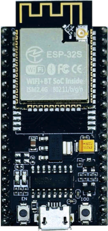
The ESP32S, manufactured by Espressif, is a low-cost, low-power system on a chip (SoC) designed for applications requiring wireless connectivity. It integrates both Wi-Fi and Bluetooth capabilities, making it a versatile choice for Internet of Things (IoT) projects, smart devices, and wireless communication systems. The ESP32S is widely appreciated for its high performance, energy efficiency, and robust feature set.
Explore Projects Built with ESP32S

Explore Projects Built with ESP32S
Common Applications and Use Cases
- IoT devices and smart home automation
- Wireless sensor networks
- Wearable electronics
- Industrial automation and control systems
- Prototyping and development of connected devices
- Real-time data monitoring and logging
Technical Specifications
The ESP32S is packed with features that make it suitable for a wide range of applications. Below are its key technical specifications:
| Parameter | Value |
|---|---|
| Manufacturer | Espressif |
| Part ID | ESP32S |
| Processor | Dual-core Xtensa® 32-bit LX6 microprocessor |
| Clock Speed | Up to 240 MHz |
| Flash Memory | 4 MB (external SPI flash) |
| SRAM | 520 KB |
| Wireless Connectivity | Wi-Fi 802.11 b/g/n, Bluetooth v4.2 + BLE |
| Operating Voltage | 3.0V to 3.6V |
| GPIO Pins | 34 (multiplexed for various functions) |
| ADC Channels | 18 (12-bit resolution) |
| DAC Channels | 2 |
| Communication Interfaces | UART, SPI, I2C, I2S, CAN, PWM |
| Power Consumption | Ultra-low power consumption in deep sleep mode (~10 µA) |
| Operating Temperature | -40°C to +85°C |
| Dimensions | 25.5 mm x 18 mm |
Pin Configuration and Descriptions
The ESP32S has a total of 38 pins, with multiple functions multiplexed on each pin. Below is a table summarizing the key pin configurations:
| Pin Number | Pin Name | Function | Description |
|---|---|---|---|
| 1 | EN | Enable | Active high; resets the chip when pulled low. |
| 2 | IO0 | GPIO0, Boot Mode | Used for boot mode selection and general GPIO. |
| 3 | IO1 | GPIO1, UART TX | UART transmit pin or general GPIO. |
| 4 | IO2 | GPIO2 | General-purpose I/O pin. |
| 5 | IO3 | GPIO3, UART RX | UART receive pin or general GPIO. |
| 6-11 | N/A | Flash SPI Pins | Reserved for SPI flash memory. |
| 12 | IO12 | GPIO12, ADC2_CH0 | General GPIO or ADC channel. |
| 13 | IO13 | GPIO13, ADC2_CH1 | General GPIO or ADC channel. |
| 14 | IO14 | GPIO14, ADC2_CH2, PWM | General GPIO, ADC, or PWM output. |
| 15 | IO15 | GPIO15, ADC2_CH3, PWM | General GPIO, ADC, or PWM output. |
| 16-34 | IO16-IO34 | GPIO, ADC, DAC, I2C, SPI, UART, PWM | Multiplexed pins for various functions. |
| 35-38 | GND, 3V3 | Ground, Power Supply | Ground and 3.3V power supply pins. |
For a complete pinout diagram, refer to the official Espressif ESP32S datasheet.
Usage Instructions
The ESP32S can be used in a variety of circuits and projects. Below are the steps and best practices for using the ESP32S:
Basic Setup
- Power Supply: Provide a stable 3.3V power supply to the ESP32S. Avoid exceeding 3.6V to prevent damage.
- Boot Mode: To upload code, connect GPIO0 to GND and reset the chip. Disconnect GPIO0 from GND after uploading.
- Programming: Use a USB-to-serial adapter (e.g., FTDI or CP2102) to connect the ESP32S to your computer. Ensure the correct drivers are installed.
Connecting to an Arduino UNO
The ESP32S can be programmed using the Arduino IDE. Follow these steps:
- Install the ESP32 board package in the Arduino IDE:
- Go to File > Preferences and add the following URL to the "Additional Board Manager URLs" field:
https://dl.espressif.com/dl/package_esp32_index.json - Open Tools > Board > Boards Manager, search for "ESP32," and install the package.
- Go to File > Preferences and add the following URL to the "Additional Board Manager URLs" field:
- Select the ESP32S board from Tools > Board.
- Write and upload your code.
Example Code: Blink an LED
The following code demonstrates how to blink an LED connected to GPIO2:
// ESP32S Blink Example
// This code blinks an LED connected to GPIO2 on the ESP32S.

#define LED_PIN 2  // Define the GPIO pin for the LED

void setup() {
  pinMode(LED_PIN, OUTPUT);  // Set GPIO2 as an output pin
}

void loop() {
  digitalWrite(LED_PIN, HIGH);  // Turn the LED on
  delay(1000);                  // Wait for 1 second
  digitalWrite(LED_PIN, LOW);   // Turn the LED off
  delay(1000);                  // Wait for 1 second
}
Best Practices
- Use level shifters if interfacing with 5V logic devices.
- Avoid leaving unused pins floating; connect them to GND or VCC as needed.
- Use decoupling capacitors (e.g., 0.1 µF) near the power pins to reduce noise.
- Ensure proper grounding to avoid communication issues.
Troubleshooting and FAQs
Common Issues
ESP32S Not Detected by Computer
- Ensure the USB-to-serial adapter drivers are installed.
- Check the connections and ensure the correct COM port is selected in the Arduino IDE.
Code Upload Fails
- Verify that GPIO0 is connected to GND during the upload process.
- Check the baud rate in the Arduino IDE (default: 115200).
Wi-Fi Connection Issues
- Ensure the correct SSID and password are used in your code.
- Check for interference or weak signal strength.
Overheating
- Verify that the input voltage does not exceed 3.6V.
- Ensure proper ventilation and avoid short circuits.
FAQs
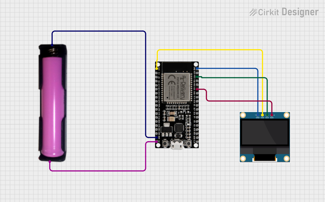
Q: Can the ESP32S operate on battery power?
A: Yes, the ESP32S can operate on battery power. Use a 3.7V LiPo battery with a voltage regulator to provide a stable 3.3V supply.
Q: How do I reset the ESP32S?
A: Press the EN (Enable) button on the module to reset the chip.
Q: Can I use the ESP32S for Bluetooth audio streaming?
A: Yes, the ESP32S supports Bluetooth audio streaming using the A2DP profile.
Q: What is the maximum range of the ESP32S Wi-Fi?
A: The range depends on the environment but typically extends up to 100 meters in open spaces.
For additional support, refer to the official Espressif documentation or community forums.