
How to Use ICL7660 Charge-Pump Voltage Converter (DIP-8): Examples, Pinouts, and Specs
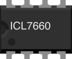
 Design with ICL7660 Charge-Pump Voltage Converter (DIP-8) in Cirkit Designer
Introduction
The ICL7660 is a charge-pump voltage converter manufactured by Renesas. It is designed to efficiently generate a negative voltage from a positive voltage supply, making it ideal for applications requiring a dual supply voltage. The device operates without the need for inductors, simplifying circuit design and reducing component count. Its compact DIP-8 package ensures easy integration into a wide range of electronic systems.
Explore Projects Built with ICL7660 Charge-Pump Voltage Converter (DIP-8)
 Open Project in Cirkit Designer
 Open Project in Cirkit Designer
 Open Project in Cirkit Designer
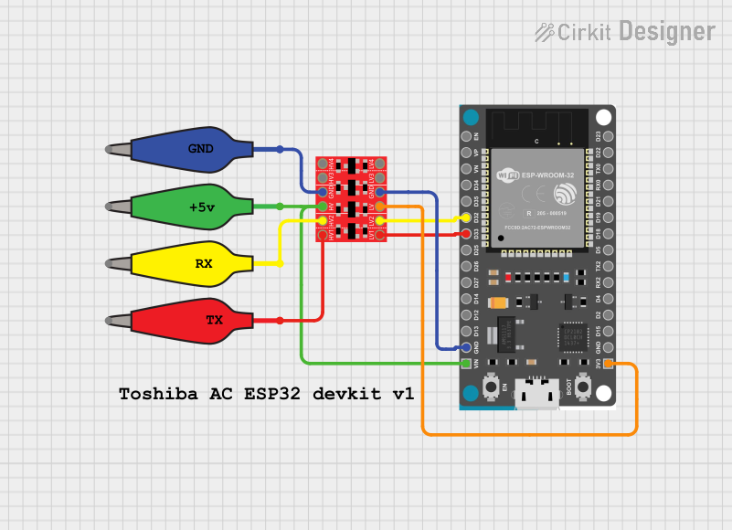 Open Project in Cirkit Designer
Explore Projects Built with ICL7660 Charge-Pump Voltage Converter (DIP-8)
Open Project in Cirkit DesignerOpen Project in Cirkit DesignerOpen Project in Cirkit DesignerOpen Project in Cirkit DesignerCommon Applications and Use Cases
- Generating a -5V supply from a +5V source
- Operational amplifier biasing
- RS232 communication systems
- Low-power analog circuits
- Battery-powered devices requiring dual voltage supplies
Technical Specifications
The following table outlines the key technical specifications of the ICL7660:
| Parameter | Value |
|---|---|
| Input Voltage Range | 1.5V to 10V |
| Output Voltage Range | -1.5V to -10V |
| Maximum Output Current | 20mA (typical) |
| Efficiency | 95% (typical, at low loads) |
| Operating Temperature Range | 0°C to +70°C |
| Package Type | DIP-8 |
Pin Configuration and Descriptions
The ICL7660 is housed in an 8-pin DIP package. The pinout and descriptions are as follows:
| Pin Number | Pin Name | Description |
|---|---|---|
| 1 | V+ | Positive power supply input (1.5V to 10V). |
| 2 | CAP+ | Positive terminal of the external charge-pump capacitor. |
| 3 | GND | Ground (0V reference). |
| 4 | CAP- | Negative terminal of the external charge-pump capacitor. |
| 5 | VOUT | Negative voltage output (-V+). |
| 6 | LV | Low-voltage pin. Connect to GND for input voltages below 3.5V. |
| 7 | OSC | Oscillator control pin. Can be used to adjust the oscillator frequency. |
| 8 | NC | No connection. Leave unconnected or use as a mechanical support point. |
Usage Instructions
How to Use the ICL7660 in a Circuit
- Power Supply: Connect the positive supply voltage (1.5V to 10V) to the V+ pin and ground to the GND pin.
- Charge-Pump Capacitor: Connect a capacitor (typically 10µF) between the CAP+ and CAP- pins. This capacitor is essential for the charge-pump operation.
- Output Capacitor: Connect another capacitor (typically 10µF) between the VOUT pin and GND to stabilize the output voltage.
- Low Voltage Operation: If the input voltage is below 3.5V, connect the LV pin to GND to ensure proper operation.
- Oscillator Adjustment (Optional): The internal oscillator frequency can be adjusted by connecting an external capacitor to the OSC pin. For most applications, this pin can be left unconnected.
Example Circuit
Below is a basic circuit diagram for generating a -5V output from a +5V input:
+5V ---- V+ (Pin 1)          CAP+ (Pin 2) ----||---- CAP- (Pin 4)
             |                                10µF
            GND (Pin 3) ---------------------- GND
             |
           VOUT (Pin 5) ----||---- GND
                             10µF
Arduino UNO Example Code
The ICL7660 can be used in Arduino projects to provide a negative voltage supply for analog circuits. Below is an example code snippet:
// Example: Using the ICL7660 to generate -5V for an analog circuit
// This code demonstrates how to read an analog signal using Arduino UNO
// and a dual-supply operational amplifier powered by the ICL7660.

const int analogPin = A0; // Analog input pin connected to the circuit

void setup() {
  Serial.begin(9600); // Initialize serial communication
  pinMode(analogPin, INPUT); // Set the analog pin as input
}

void loop() {
  int sensorValue = analogRead(analogPin); // Read the analog signal
  float voltage = sensorValue * (5.0 / 1023.0); // Convert to voltage
  Serial.print("Analog Voltage: ");
  Serial.println(voltage); // Print the voltage to the Serial Monitor
  delay(500); // Wait for 500ms before the next reading
}
Important Considerations and Best Practices
- Use low-ESR capacitors (e.g., ceramic or tantalum) for optimal performance.
- Ensure the input voltage does not exceed the maximum rating of 10V.
- For input voltages below 3.5V, always connect the LV pin to GND.
- Avoid exceeding the maximum output current of 20mA to prevent voltage drops and instability.
- Keep the charge-pump and output capacitors as close as possible to the IC to minimize noise and improve efficiency.
Troubleshooting and FAQs
Common Issues and Solutions
Output Voltage is Incorrect or Unstable
- Verify that the charge-pump capacitor (CAP+ to CAP-) and output capacitor (VOUT to GND) are properly connected and have the correct values (typically 10µF).
- Ensure the input voltage is within the specified range (1.5V to 10V).
- Check for loose connections or damaged components.
Excessive Voltage Ripple
- Use low-ESR capacitors to reduce ripple.
- Increase the capacitance of the output capacitor if necessary.
IC Overheating
- Ensure the output current does not exceed 20mA.
- Check for short circuits at the output.
No Output Voltage
- Confirm that the LV pin is connected to GND if the input voltage is below 3.5V.
- Verify that the V+ and GND pins are correctly connected to the power supply.
FAQs
Q: Can the ICL7660 generate a positive voltage?
A: No, the ICL7660 is specifically designed to generate a negative voltage from a positive input. For positive voltage generation, consider using a boost converter.
Q: What happens if I use capacitors with values other than 10µF?
A: The ICL7660 can operate with different capacitor values, but performance (e.g., output stability and ripple) may vary. It is recommended to use 10µF capacitors for typical applications.
Q: Can I use the ICL7660 with a 12V input?
A: No, the maximum input voltage for the ICL7660 is 10V. Exceeding this limit may damage the IC.
Q: Is the ICL7660 suitable for high-current applications?
A: No, the ICL7660 is designed for low-current applications with a maximum output current of 20mA. For higher currents, consider using a different voltage converter.
This concludes the documentation for the ICL7660 Charge-Pump Voltage Converter (DIP-8).