How to Use ULN2003A: Examples, Pinouts, and Specs
Introduction
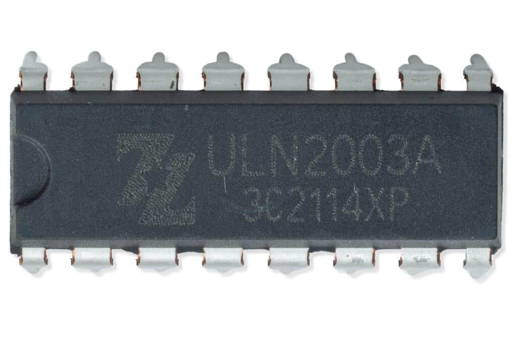
The ULN2003A, manufactured by Texas Instruments, is a high-voltage, high-current Darlington transistor array. It consists of seven NPN Darlington pairs, each capable of driving loads up to 500mA and withstanding voltages up to 50V. The component is designed to simplify the control of high-power devices such as relays, stepper motors, and other inductive loads. Its built-in freewheeling diodes make it particularly suitable for handling inductive loads, protecting the circuit from voltage spikes.
Explore Projects Built with ULN2003A

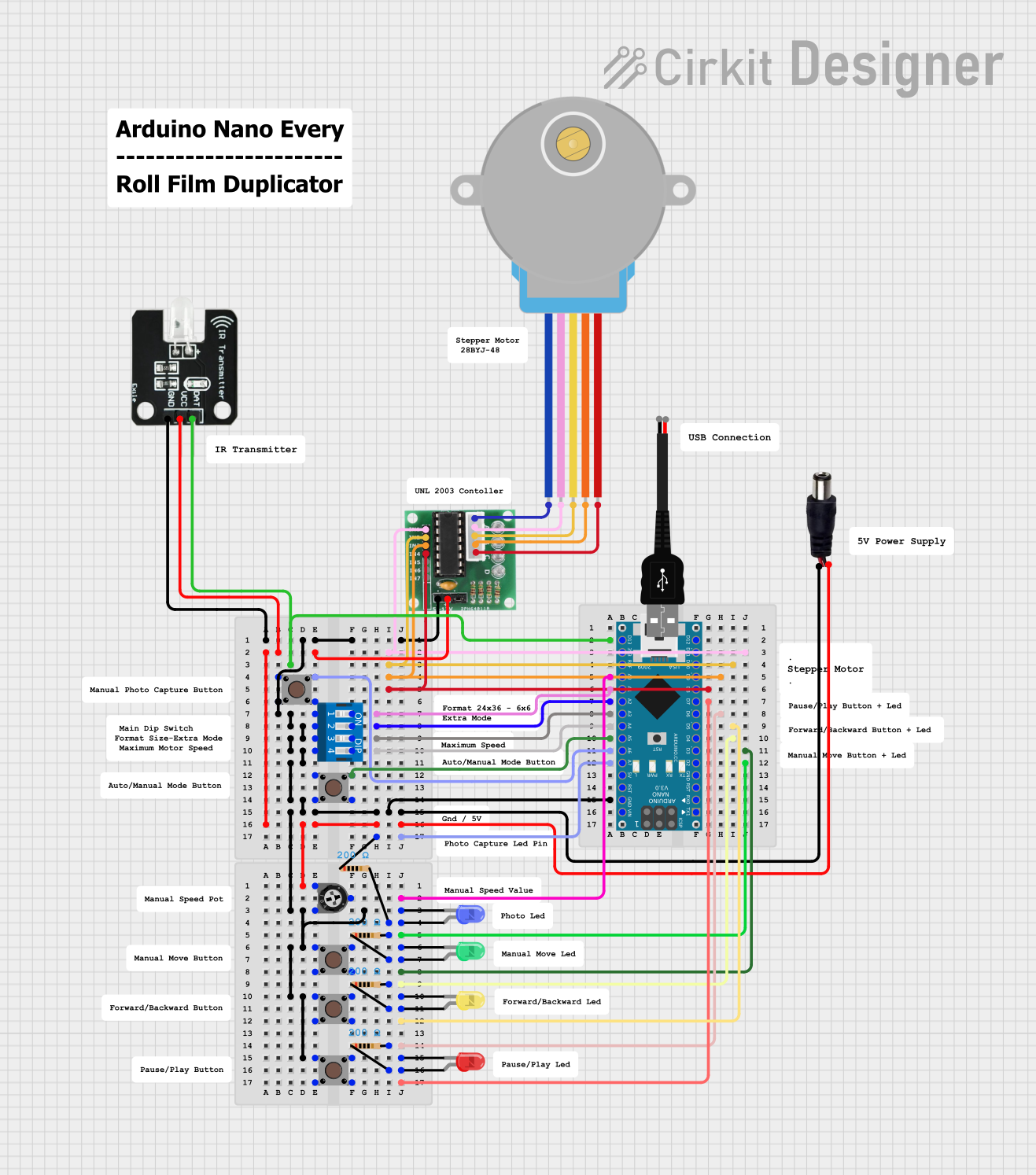
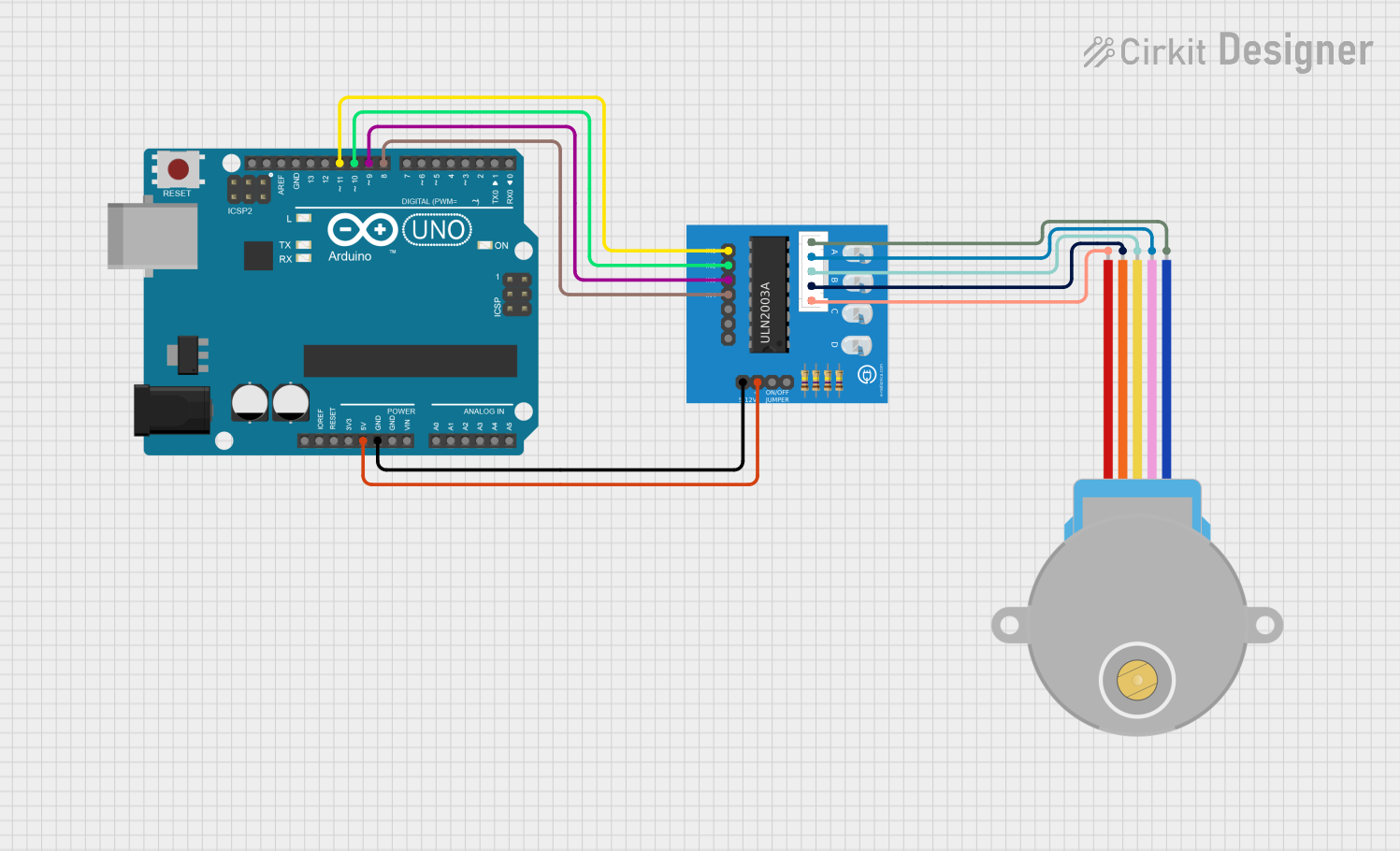
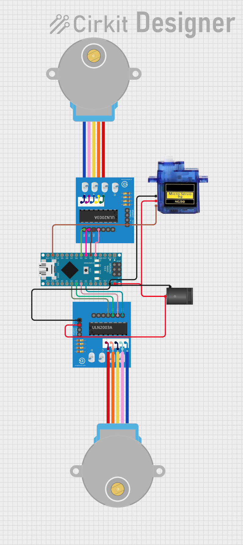
Explore Projects Built with ULN2003A
Common Applications
- Driving relays in automation systems
- Controlling stepper motors in robotics
- Powering LED arrays
- Interfacing microcontrollers with high-power devices
- Industrial control systems
Technical Specifications
Key Technical Details
- Supply Voltage (VCE): Up to 50V
- Output Current (per channel): Up to 500mA
- Input Voltage (VIH): 2.4V (minimum for logic HIGH)
- Output Clamp Diodes: Built-in for inductive load protection
- Number of Channels: 7
- Package Types: DIP-16, SOIC-16, and others
- Operating Temperature Range: -20°C to 85°C
Pin Configuration and Descriptions
The ULN2003A is typically available in a 16-pin DIP or SOIC package. Below is the pinout and description:
| Pin Number | Pin Name | Description |
|---|---|---|
| 1-7 | Input 1-7 | Logic inputs for each Darlington pair. Connect to a microcontroller or logic circuit. |
| 8 | GND | Ground pin. Connect to the ground of the power supply. |
| 9-15 | Output 1-7 | Outputs for each Darlington pair. Connect to the load (e.g., relay, motor). |
| 16 | COM (Common) | Common cathode for the freewheeling diodes. Connect to the positive supply of the load. |
Usage Instructions
How to Use the ULN2003A in a Circuit
Power Supply:
- Ensure the load voltage does not exceed 50V and the current per channel is within 500mA.
- Connect the ground pin (Pin 8) to the ground of the power supply.
Input Connections:
- Connect the input pins (Pins 1-7) to the control signals from a microcontroller or logic circuit.
- A logic HIGH (≥2.4V) at an input pin will activate the corresponding output pin.
Output Connections:
- Connect the load (e.g., relay, motor) to the output pins (Pins 9-15).
- The other terminal of the load should be connected to the positive supply voltage.
Freewheeling Diodes:
- The ULN2003A includes built-in diodes to protect against voltage spikes from inductive loads.
- Connect the COM pin (Pin 16) to the positive supply voltage of the load.
Example: Controlling a Relay with Arduino UNO
Below is an example of how to use the ULN2003A to control a relay with an Arduino UNO:
// Define the input pin connected to the ULN2003A
const int relayControlPin = 7; // Pin 7 of Arduino connected to ULN2003A Input 1

void setup() {
  pinMode(relayControlPin, OUTPUT); // Set the pin as an output
}

void loop() {
  digitalWrite(relayControlPin, HIGH); // Turn the relay ON
  delay(1000); // Wait for 1 second
  digitalWrite(relayControlPin, LOW);  // Turn the relay OFF
  delay(1000); // Wait for 1 second
}
Important Considerations
- Current Limitation: Ensure the total current drawn by all channels does not exceed the package limit.
- Heat Dissipation: If driving high-current loads, consider heat dissipation and use proper cooling if necessary.
- COM Pin Connection: Always connect the COM pin to the positive supply voltage of the load to enable the freewheeling diodes.
Troubleshooting and FAQs
Common Issues and Solutions
Problem: The load is not turning on.
- Solution: Check the input voltage to ensure it meets the minimum logic HIGH threshold (2.4V). Verify the connections to the load and power supply.
Problem: The ULN2003A is overheating.
- Solution: Ensure the current per channel does not exceed 500mA. If multiple channels are active, ensure the total current is within the package limit. Add a heatsink if necessary.
Problem: Voltage spikes damaging the circuit.
- Solution: Verify that the COM pin is properly connected to the positive supply voltage of the load. This enables the built-in freewheeling diodes to protect against voltage spikes.
Problem: The relay or motor is not functioning correctly.
- Solution: Check the load specifications to ensure compatibility with the ULN2003A. Verify that the power supply voltage and current are sufficient for the load.
FAQs
Q1: Can the ULN2003A drive a stepper motor?
A1: Yes, the ULN2003A is commonly used to drive stepper motors. Each channel can control one coil of the motor, and multiple channels can be used together for multi-phase stepper motors.
Q2: Do I need external diodes for inductive loads?
A2: No, the ULN2003A includes built-in freewheeling diodes to protect against voltage spikes from inductive loads.
Q3: Can I use the ULN2003A with a 3.3V microcontroller?
A3: Yes, but ensure the input voltage from the microcontroller meets the minimum logic HIGH threshold (2.4V). If not, consider using a level shifter.
Q4: What happens if I exceed the current rating?
A4: Exceeding the current rating can cause overheating and potential damage to the ULN2003A. Always operate within the specified limits.
This concludes the documentation for the ULN2003A. For further details, refer to the official datasheet provided by Texas Instruments.