How to Use ESP32: Examples, Pinouts, and Specs
Introduction
The ESP32 is a low-cost, low-power system on a chip (SoC) developed by Espressif Systems. It features integrated Wi-Fi and Bluetooth capabilities, making it an ideal choice for Internet of Things (IoT) applications, smart devices, and embedded systems. The ESP32 is highly versatile, offering dual-core processing, a wide range of GPIO pins, and support for various communication protocols.
Explore Projects Built with ESP32


Explore Projects Built with ESP32
Common Applications and Use Cases
- IoT devices (e.g., smart home automation, sensors, and actuators)
- Wearable technology
- Wireless communication hubs
- Robotics and drones
- Data logging and remote monitoring
- Prototyping and educational projects
Technical Specifications
The ESP32 is packed with features that make it a powerful and flexible component for a wide range of applications. Below are its key technical specifications:
General Specifications
- Processor: Dual-core Xtensa® 32-bit LX6 microprocessor
- Clock Speed: Up to 240 MHz
- RAM: 520 KB SRAM
- Flash Memory: Typically 4 MB (varies by module)
- Wi-Fi: 802.11 b/g/n (2.4 GHz)
- Bluetooth: v4.2 BR/EDR and BLE
- Operating Voltage: 3.3V
- GPIO Pins: 34 (multipurpose, including ADC, DAC, PWM, I2C, SPI, UART)
- Power Consumption: Ultra-low power consumption in deep sleep mode (~10 µA)
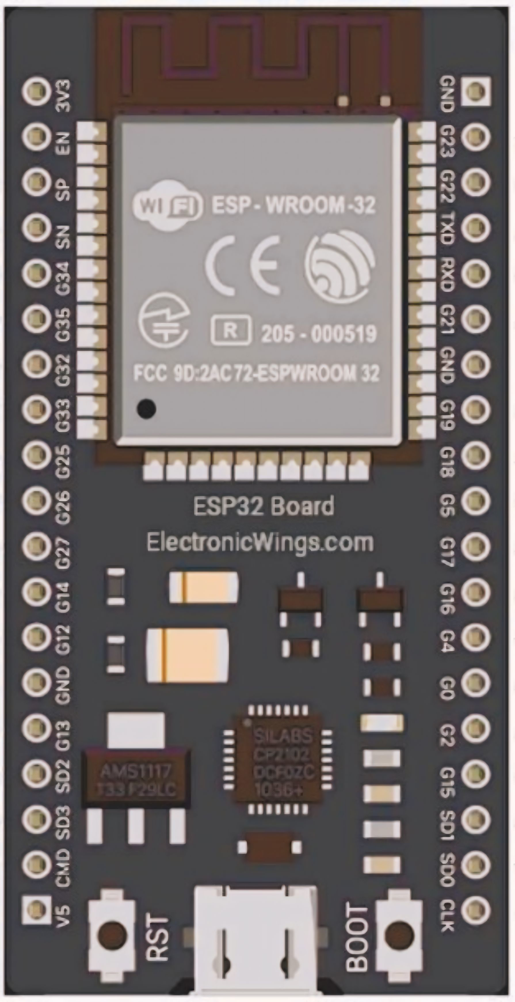
Pin Configuration and Descriptions
The ESP32 has multiple GPIO pins, each capable of serving various functions. Below is a table summarizing the key pins and their descriptions:
| Pin Name | Function | Description |
|---|---|---|
| GPIO0 | Input/Output, Boot Mode Selection | Used for boot mode selection during startup. |
| GPIO2 | Input/Output, ADC, DAC | General-purpose pin, supports ADC and DAC. |
| GPIO12 | Input/Output, ADC, Touch Sensor | Can be used as an ADC input or touch sensor. |
| GPIO13 | Input/Output, PWM, Touch Sensor | Supports PWM and touch sensing. |
| GPIO15 | Input/Output, ADC, PWM | General-purpose pin with ADC and PWM support. |
| EN | Enable | Active-high pin to enable or reset the chip. |
| 3V3 | Power | Provides 3.3V power output. |
| GND | Ground | Ground connection. |
| TX0 (GPIO1) | UART Transmit | Default UART transmit pin. |
| RX0 (GPIO3) | UART Receive | Default UART receive pin. |
Note: The ESP32 has many more GPIO pins and features. Refer to the official datasheet for a complete pinout.
Usage Instructions
How to Use the ESP32 in a Circuit
- Powering the ESP32:
- The ESP32 operates at 3.3V. Ensure your power supply provides a stable 3.3V to the
3V3pin. - Avoid supplying 5V directly to the GPIO pins, as this may damage the chip.
- The ESP32 operates at 3.3V. Ensure your power supply provides a stable 3.3V to the
- Connecting to a Computer:
- Use a USB-to-serial adapter or a development board (e.g., ESP32 DevKit) to connect the ESP32 to your computer.
- Install the necessary drivers (e.g., CP2102 or CH340) if required.
- Programming the ESP32:
- Use the Arduino IDE or Espressif's ESP-IDF (Espressif IoT Development Framework) to write and upload code.
- Select the correct board and port in the IDE before uploading.
Example: Blinking an LED with Arduino IDE
Below is an example of how to blink an LED connected to GPIO2 using the Arduino IDE:
// Define the GPIO pin where the LED is connected
const int ledPin = 2;

void setup() {
  // Set the LED pin as an output
  pinMode(ledPin, OUTPUT);
}

void loop() {
  // Turn the LED on
  digitalWrite(ledPin, HIGH);
  delay(1000); // Wait for 1 second

  // Turn the LED off
  digitalWrite(ledPin, LOW);
  delay(1000); // Wait for 1 second
}
Important Considerations and Best Practices
- Voltage Levels: Ensure all connected peripherals operate at 3.3V logic levels.
- Deep Sleep Mode: Use deep sleep mode to conserve power in battery-powered applications.
- Boot Mode: Avoid pulling GPIO0, GPIO2, or GPIO15 to the wrong state during boot, as this may prevent the ESP32 from starting correctly.
- Heat Management: The ESP32 can get warm during operation. Ensure proper ventilation or heat dissipation if used in high-performance applications.
Troubleshooting and FAQs
Common Issues and Solutions
ESP32 Not Detected by Computer:
- Ensure the correct drivers (e.g., CP2102 or CH340) are installed.
- Check the USB cable for data transfer capability (some cables are power-only).
- Verify the ESP32 is powered correctly.
Code Upload Fails:
- Ensure the correct board and port are selected in the Arduino IDE.
- Press and hold the
BOOTbutton on the ESP32 while uploading the code.
Wi-Fi Connection Issues:
- Double-check the SSID and password in your code.
- Ensure the Wi-Fi network operates on the 2.4 GHz band (ESP32 does not support 5 GHz).
Random Resets or Instability:
- Verify the power supply provides sufficient current (at least 500 mA).
- Check for loose connections or short circuits.
FAQs
Q: Can the ESP32 operate on 5V?
A: No, the ESP32 operates at 3.3V. However, many development boards include a voltage regulator that allows powering the board with 5V via the USB port.
Q: How do I use Bluetooth on the ESP32?
A: The ESP32 supports both Bluetooth Classic and BLE. Use the BluetoothSerial library for Bluetooth Classic or the BLE library for BLE in the Arduino IDE.
Q: What is the maximum range of the ESP32's Wi-Fi?
A: The range depends on environmental factors but typically extends up to 100 meters in open spaces.
Q: Can I use the ESP32 with batteries?
A: Yes, the ESP32 is suitable for battery-powered applications. Use a 3.7V LiPo battery with a voltage regulator or a development board with built-in battery support.
By following this documentation, you can effectively integrate the ESP32 into your projects and troubleshoot common issues. For more advanced features, refer to the official Espressif documentation.