
How to Use USB Connectors: Examples, Pinouts, and Specs
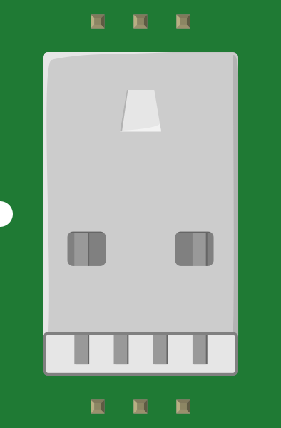
 Design with USB Connectors in Cirkit Designer
Introduction
USB (Universal Serial Bus) connectors are standardized interfaces designed for connecting electronic devices to computers, peripherals, and power sources. They facilitate data transfer, device communication, and power delivery. USB connectors are widely used in consumer electronics, including smartphones, laptops, printers, external storage devices, and more. Their versatility and ease of use have made them a universal standard in modern electronics.
Explore Projects Built with USB Connectors
 Open Project in Cirkit Designer
 Open Project in Cirkit Designer
 Open Project in Cirkit Designer
 Open Project in Cirkit Designer
Explore Projects Built with USB Connectors
Open Project in Cirkit DesignerOpen Project in Cirkit DesignerOpen Project in Cirkit DesignerOpen Project in Cirkit DesignerCommon Applications and Use Cases
- Data Transfer: Connecting external storage devices, cameras, and other peripherals to computers.
- Power Delivery: Charging smartphones, tablets, and other portable devices.
- Peripheral Connectivity: Linking keyboards, mice, printers, and game controllers to computers.
- Audio/Video Transmission: Used in USB-C for transmitting audio and video signals to monitors or TVs.
- Embedded Systems: Providing communication and power in microcontroller-based projects.
Technical Specifications
Key Technical Details
- Voltage Rating: 5V (standard), up to 20V for USB Power Delivery (USB-PD).
- Current Rating:
- USB 2.0: Up to 500mA.
- USB 3.0: Up to 900mA.
- USB-C with USB-PD: Up to 5A.
- Data Transfer Speeds:
- USB 2.0: Up to 480 Mbps.
- USB 3.0: Up to 5 Gbps.
- USB 3.1: Up to 10 Gbps.
- USB 3.2: Up to 20 Gbps.
- USB4: Up to 40 Gbps.
- Connector Types: USB-A, USB-B, Mini-USB, Micro-USB, USB-C.
Pin Configuration and Descriptions
USB-A Connector (Standard)
| Pin Number | Name | Description |
|---|---|---|
| 1 | VBUS | +5V Power Supply |
| 2 | D- | Data Line (Negative) |
| 3 | D+ | Data Line (Positive) |
| 4 | GND | Ground |
USB-C Connector
| Pin Number | Name | Description |
|---|---|---|
| A1, B1 | GND | Ground |
| A2, B2 | TX1+ | SuperSpeed Differential Pair (Positive) |
| A3, B3 | TX1- | SuperSpeed Differential Pair (Negative) |
| A4, B4 | VBUS | Power Supply (Up to 20V) |
| A5, B5 | CC1, CC2 | Configuration Channel |
| A6, B6 | D+ | USB 2.0 Data Line (Positive) |
| A7, B7 | D- | USB 2.0 Data Line (Negative) |
| A8, B8 | RX1- | SuperSpeed Differential Pair (Negative) |
| A9, B9 | RX1+ | SuperSpeed Differential Pair (Positive) |
Usage Instructions
How to Use USB Connectors in a Circuit
- Identify the Connector Type: Determine the type of USB connector (e.g., USB-A, USB-C) required for your application.
- Connect Power and Ground: Ensure the VBUS pin is connected to a 5V power source (or higher for USB-PD) and the GND pin is connected to the circuit ground.
- Data Lines: Connect the D+ and D- pins to the corresponding data lines of your device or microcontroller.
- For USB-C: Use the CC pins to negotiate power delivery and data roles if required.
- Soldering: Carefully solder the connector to the PCB, ensuring no short circuits between pins.
Important Considerations and Best Practices
- Voltage and Current Ratings: Ensure the power source matches the voltage and current requirements of the connected device.
- Cable Quality: Use high-quality USB cables to avoid data loss or power inefficiency.
- USB-C Orientation: USB-C connectors are reversible, but ensure proper pin mapping for correct functionality.
- ESD Protection: Add ESD protection diodes to the data lines to safeguard against electrostatic discharge.
- Power Delivery: For USB-PD applications, use a USB-PD controller IC to manage voltage and current negotiation.
Example: Connecting a USB Device to an Arduino UNO
/* Example code for reading data from a USB device connected to an Arduino UNO.
   Note: The Arduino UNO requires a USB host shield to interface with USB devices. */

#include <USBHost.h> // Include USB Host library

USBHost usb; // Create USBHost object

void setup() {
  Serial.begin(9600); // Initialize serial communication
  while (!Serial);    // Wait for the serial port to connect
  Serial.println("USB Host Initialized");

  if (usb.begin()) {
    Serial.println("USB Device Connected");
  } else {
    Serial.println("Failed to initialize USB Host");
  }
}

void loop() {
  usb.Task(); // Handle USB tasks
  // Add code here to interact with the connected USB device
}
Troubleshooting and FAQs
Common Issues
No Power to the Device:
- Cause: Incorrect connection of VBUS or GND pins.
- Solution: Verify the power and ground connections.
Data Transfer Fails:
- Cause: Misaligned or damaged data lines (D+ and D-).
- Solution: Check the soldering and continuity of the data lines.
USB-C Device Not Recognized:
- Cause: Missing or incorrect configuration of CC pins.
- Solution: Ensure proper pull-up or pull-down resistors on CC pins.
Overheating:
- Cause: Exceeding current rating of the connector.
- Solution: Use a connector rated for higher current or reduce the load.
FAQs
Q: Can I use a USB-C connector for USB 2.0 devices?
A: Yes, USB-C connectors are backward compatible with USB 2.0, but ensure proper pin mapping.Q: What is the maximum cable length for USB?
A: For USB 2.0, the maximum recommended length is 5 meters. For USB 3.0 and higher, it is typically 3 meters.Q: How do I implement USB Power Delivery (USB-PD)?
A: Use a USB-PD controller IC to negotiate voltage and current levels with the connected device.Q: Can USB connectors be used for audio and video transmission?
A: Yes, USB-C supports audio and video transmission using protocols like DisplayPort over USB-C.