How to Use ESP32 Devkit V1: Examples, Pinouts, and Specs
Introduction
The ESP32 Devkit V1, manufactured by Espressif, is a versatile development board built around the powerful ESP32 chip. It features integrated Wi-Fi and Bluetooth capabilities, making it an excellent choice for Internet of Things (IoT) applications, smart devices, and rapid prototyping. With its dual-core processor, low power consumption, and extensive GPIO options, the ESP32 Devkit V1 is suitable for a wide range of projects, from home automation to industrial monitoring.
Explore Projects Built with ESP32 Devkit V1


Explore Projects Built with ESP32 Devkit V1
Common Applications and Use Cases
- IoT devices and smart home systems
- Wireless sensor networks
- Wearable technology
- Robotics and automation
- Prototyping for Bluetooth and Wi-Fi-enabled devices
- Data logging and remote monitoring
Technical Specifications
The ESP32 Devkit V1 is designed to provide robust performance and flexibility. Below are its key technical specifications:
| Parameter | Value |
|---|---|
| Microcontroller | ESP32-D0WDQ6 (dual-core Xtensa® 32-bit LX6 microprocessor) |
| Clock Speed | Up to 240 MHz |
| Flash Memory | 4 MB (varies by model) |
| SRAM | 520 KB |
| Wireless Connectivity | Wi-Fi 802.11 b/g/n, Bluetooth v4.2 + BLE |
| Operating Voltage | 3.3V |
| Input Voltage (VIN) | 5V (via USB or external power supply) |
| GPIO Pins | 30 (varies slightly by board version) |
| ADC Channels | 18 (12-bit resolution) |
| DAC Channels | 2 (8-bit resolution) |
| Communication Interfaces | UART, SPI, I2C, I2S, CAN, PWM |
| Power Consumption | Ultra-low power consumption with multiple power modes |
| Dimensions | Approx. 54 mm x 27 mm |
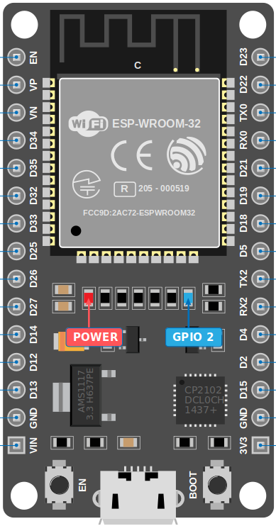
Pin Configuration and Descriptions
The ESP32 Devkit V1 features a 30-pin layout. Below is the pin configuration:
| Pin Number | Pin Name | Description |
|---|---|---|
| 1 | EN | Enable pin. Pulling this pin low resets the chip. |
| 2 | IO23 | GPIO23, can be used for digital I/O or SPI MOSI. |
| 3 | IO22 | GPIO22, commonly used as I2C SCL. |
| 4 | IO21 | GPIO21, commonly used as I2C SDA. |
| 5 | GND | Ground pin. |
| 6 | VIN | Input voltage (5V) for powering the board. |
| 7 | IO19 | GPIO19, can be used for digital I/O or SPI MISO. |
| 8 | IO18 | GPIO18, can be used for digital I/O or SPI SCK. |
| 9 | IO17 | GPIO17, general-purpose digital I/O. |
| 10 | IO16 | GPIO16, general-purpose digital I/O. |
| ... | ... | ... |
| 30 | IO0 | GPIO0, used for boot mode selection during programming. |
Note: The exact pinout may vary slightly depending on the specific version of the ESP32 Devkit V1. Always refer to the datasheet for your specific board.
Usage Instructions
How to Use the ESP32 Devkit V1 in a Circuit
Powering the Board:
- Connect the board to your computer via a micro-USB cable for power and programming.
- Alternatively, supply 5V to the VIN pin and connect GND to the ground of your power source.
Programming the Board:
- Install the Arduino IDE and add the ESP32 board support package.
- Select the correct board (
ESP32 Dev Module) and COM port in the Arduino IDE. - Write your code and upload it to the board.
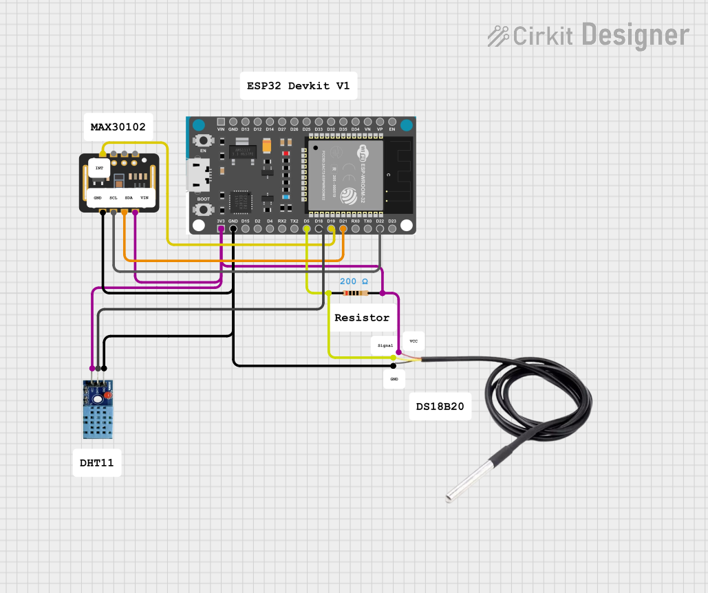
Connecting Peripherals:
- Use the GPIO pins to connect sensors, actuators, or other peripherals.
- Ensure that the voltage levels of connected devices are compatible with the ESP32's 3.3V logic.
Wi-Fi and Bluetooth Setup:
- Use the built-in libraries (
WiFi.handBluetoothSerial.h) to configure wireless communication.
- Use the built-in libraries (
Important Considerations and Best Practices
- Voltage Levels: The ESP32 operates at 3.3V logic. Avoid connecting 5V signals directly to its GPIO pins.
- Boot Mode: Ensure GPIO0 is pulled low during programming to enter boot mode.
- Power Supply: Use a stable power source to avoid unexpected resets or performance issues.
- Heat Management: The ESP32 may heat up during operation. Ensure proper ventilation if used in enclosed spaces.
Example Code for Arduino IDE
Below is an example of how to connect the ESP32 Devkit V1 to a Wi-Fi network and blink an LED:
#include <WiFi.h> // Include the Wi-Fi library

const char* ssid = "Your_SSID";       // Replace with your Wi-Fi network name
const char* password = "Your_Password"; // Replace with your Wi-Fi password
const int ledPin = 2;                 // Built-in LED pin (GPIO2)

void setup() {
  Serial.begin(115200);               // Initialize serial communication
  pinMode(ledPin, OUTPUT);            // Set LED pin as output

  // Connect to Wi-Fi
  Serial.print("Connecting to Wi-Fi");
  WiFi.begin(ssid, password);
  while (WiFi.status() != WL_CONNECTED) {
    delay(500);
    Serial.print(".");
  }
  Serial.println("\nWi-Fi connected!");
  Serial.print("IP Address: ");
  Serial.println(WiFi.localIP());     // Print the device's IP address
}

void loop() {
  digitalWrite(ledPin, HIGH);         // Turn the LED on
  delay(1000);                        // Wait for 1 second
  digitalWrite(ledPin, LOW);          // Turn the LED off
  delay(1000);                        // Wait for 1 second
}
Troubleshooting and FAQs
Common Issues and Solutions
The board is not detected by the computer:
- Ensure the USB cable is functional and supports data transfer.
- Install the correct USB-to-serial driver (e.g., CP2102 or CH340, depending on your board).
Upload fails with a timeout error:
- Check that the correct board and COM port are selected in the Arduino IDE.
- Hold the
BOOTbutton on the board while uploading the code.
Wi-Fi connection fails:
- Double-check the SSID and password in your code.
- Ensure the Wi-Fi network is operational and within range.
GPIO pins not working as expected:
- Verify that the pins are not being used for other functions (e.g., boot mode).
- Check for short circuits or incorrect wiring.
FAQs
Q: Can I power the ESP32 Devkit V1 with a battery?
A: Yes, you can use a 3.7V LiPo battery connected to the 3.3V pin or a 5V source connected to the VIN pin.Q: How do I reset the board?
A: Press theENbutton to reset the board.Q: Can I use the ESP32 Devkit V1 with MicroPython?
A: Yes, the ESP32 supports MicroPython. You can flash the MicroPython firmware to the board and use it for programming.Q: What is the maximum range of the Wi-Fi module?
A: The Wi-Fi range depends on environmental factors but typically extends up to 100 meters in open spaces.
By following this documentation, you can effectively utilize the ESP32 Devkit V1 for your projects and troubleshoot common issues with ease.