How to Use 12V/24V 6-Way Blade Fuse Block with LED Indicator: Examples, Pinouts, and Specs
Introduction
The 12V/24V 6-Way Blade Fuse Block with LED Indicator is a compact and efficient solution for managing multiple electrical circuits in automotive, marine, and other 12V or 24V systems. This fuse block can accommodate up to six standard blade fuses, providing a centralized and organized way to protect circuits from overcurrent. The built-in LED indicators simplify troubleshooting by illuminating when a fuse is blown, allowing for quick identification and replacement.
Explore Projects Built with 12V/24V 6-Way Blade Fuse Block with LED Indicator


Explore Projects Built with 12V/24V 6-Way Blade Fuse Block with LED Indicator
Common Applications and Use Cases
- Automotive electrical systems (cars, trucks, RVs)
- Marine electrical systems (boats, yachts)
- Off-grid solar power systems
- Industrial equipment and machinery
- DIY electronics projects requiring multiple fused circuits
Technical Specifications
Key Technical Details
- Operating Voltage: 12V DC or 24V DC
- Maximum Current per Circuit: 30A
- Maximum Total Current: 100A
- Fuse Type: Standard blade fuses (ATO/ATC)
- LED Indicator: Lights up when a fuse is blown
- Input Terminals: 1 positive input terminal, 1 negative input terminal
- Output Terminals: 6 positive output terminals, 6 negative output terminals
- Material: Flame-retardant plastic housing
- Mounting: Screw holes for secure installation
- Dimensions: Approximately 3.9 x 2.8 x 1.4 inches (100 x 70 x 35 mm)
Pin Configuration and Descriptions
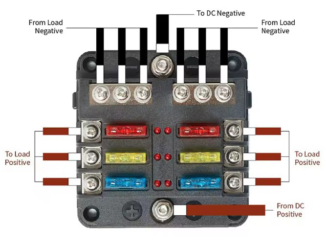
The fuse block has a straightforward layout with input and output terminals for both positive and negative connections. Below is a detailed description:
| Pin/Terminal | Description |
|---|---|
| Positive Input | Connects to the positive terminal of the power source (12V or 24V). |
| Negative Input | Connects to the negative terminal (ground) of the power source. |
| Positive Outputs | Six terminals for connecting the positive wires of individual circuits. |
| Negative Outputs | Six terminals for connecting the negative wires of individual circuits. |
| Fuse Slots | Six slots for standard blade fuses (one per circuit). |
| LED Indicators | One LED per fuse slot; lights up when the corresponding fuse is blown. |
Usage Instructions
How to Use the Component in a Circuit
Mount the Fuse Block:
- Secure the fuse block to a flat surface using screws through the mounting holes.
- Ensure the location is dry and protected from excessive vibration or heat.
Connect the Power Source:
- Attach the positive input terminal to the positive terminal of the power source (e.g., car battery).
- Attach the negative input terminal to the negative terminal (ground) of the power source.
Install Blade Fuses:
- Insert the appropriate blade fuse into each slot based on the current rating of the connected circuit.
- Ensure the fuse rating matches the load requirements to prevent overcurrent damage.
Connect Circuits:
- Connect the positive wires of your circuits to the positive output terminals.
- Connect the negative wires of your circuits to the negative output terminals.
Test the Setup:
- Power on the system and verify that all circuits are functioning correctly.
- If a circuit is not working, check the corresponding LED indicator to see if the fuse is blown.
Important Considerations and Best Practices
- Always use fuses with the correct current rating for each circuit to avoid damage to connected devices.
- Ensure all connections are secure to prevent loose wires, which can cause electrical faults.
- Regularly inspect the fuse block for signs of wear, corrosion, or damage.
- If using in a vehicle, ensure the fuse block is mounted in a location that is easily accessible for maintenance.
Example: Connecting to an Arduino UNO
If you are using the fuse block to power multiple devices in an Arduino project, follow these steps:
- Connect the positive input terminal of the fuse block to the 12V power supply.
- Use one of the positive output terminals to power the Arduino UNO via its VIN pin.
- Use other output terminals to power additional devices (e.g., sensors, motors) connected to the Arduino.
Here is an example Arduino sketch to monitor a sensor powered through the fuse block:
// Example Arduino code to read a sensor powered via the fuse block
const int sensorPin = A0;  // Analog pin connected to the sensor
int sensorValue = 0;       // Variable to store the sensor reading

void setup() {
  Serial.begin(9600);  // Initialize serial communication
  pinMode(sensorPin, INPUT);  // Set the sensor pin as input
}

void loop() {
  sensorValue = analogRead(sensorPin);  // Read the sensor value
  Serial.print("Sensor Value: ");
  Serial.println(sensorValue);  // Print the sensor value to the Serial Monitor
  delay(1000);  // Wait for 1 second before the next reading
}
Troubleshooting and FAQs
Common Issues and Solutions
LED Indicator Does Not Light Up When a Fuse is Blown:
- Cause: The LED circuit may not be receiving power.
- Solution: Check the input connections to ensure the fuse block is properly powered.
Fuse Blows Repeatedly:
- Cause: The connected circuit may be drawing more current than the fuse rating.
- Solution: Verify the current requirements of the circuit and use a fuse with an appropriate rating.
No Power to Connected Circuits:
- Cause: Loose or incorrect wiring.
- Solution: Double-check all connections, ensuring they are secure and correctly placed.
Corrosion on Terminals:
- Cause: Exposure to moisture or harsh environments.
- Solution: Clean the terminals with a contact cleaner and consider relocating the fuse block to a drier location.
FAQs
Q: Can I use this fuse block for AC circuits?
A: No, this fuse block is designed for DC circuits only, specifically 12V or 24V systems.
Q: What happens if I install a fuse with a higher rating than required?
A: Using a fuse with a higher rating can result in insufficient protection for the circuit, potentially causing damage to connected devices.
Q: Can I use fewer than six fuses?
A: Yes, you can use as many or as few fuses as needed. Unused slots will remain inactive.
Q: Is the fuse block waterproof?
A: No, the fuse block is not waterproof. It should be installed in a dry and protected location.